Mitsubishi Montero (2002-2004). Manual - part 717


  Index      Mitsubishi     Mitsubishi Montero - service repair manual 2002-2004 year


Search            


Content   ..  715  716  717  718   ..


Mitsubishi Montero (2002-2004). Manual - part 717


TSB Revision

DIAGNOSTIC TROUBLE CODE PROCEDURES

13Ac-565

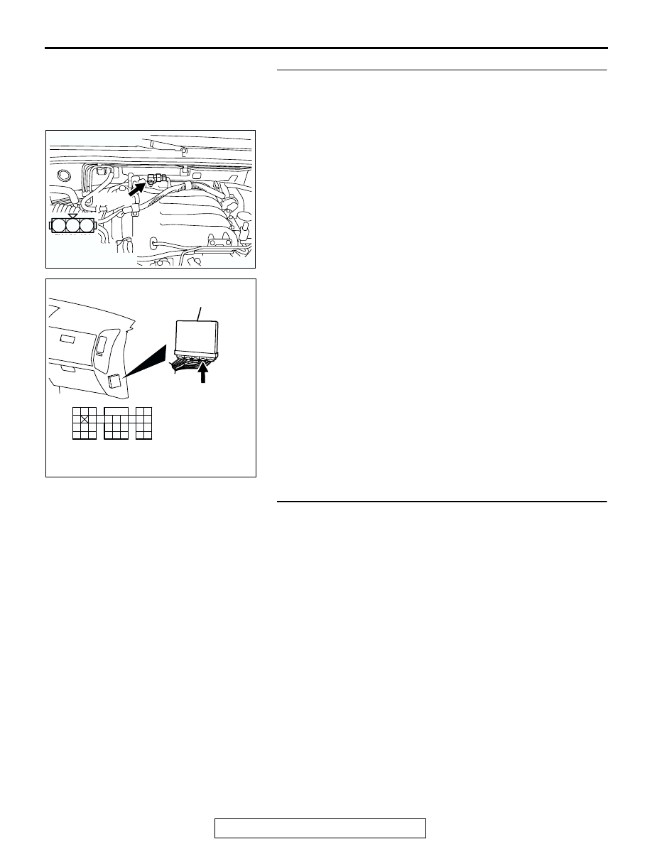
STEP 11. Check for open circuit and short circuit to ground 
and harness damage between manifold differential 
pressure sensor connector B-28 (terminal No. 1) and PCM 
connector D-135 (terminal No. 101).
Q: Is the harness wire in good condition?

YES : Replace the manifold differential pressure sensor. 

Then go to Step 12.

NO :  Repair it. Then go to Step 12.

STEP 12. Test the OBD-II drive cycle.
(1) Carry out a test drive with the drive cycle pattern. Refer to 

GROUP 13A, Procedure 6 

− Other Monitor 

P.13Ab-2

.

(2) Check the diagnostic trouble code (DTC).
Q: Is DTC P1400 set?

YES : Retry the troubleshooting.
NO :  The inspection is complete.

AK200975

1

2

3

AB

HARNESS 
CONNECTOR: 
COMPONENT SIDE

CONNECTOR: B-28

B-28(B)

AK200947

91

92

93

94

95

96

97

98

99

100

101

102

103

104

105

106

107

108

109

110

111

112

113

114

115

116

117

118

119

120

CONNECTOR: D-135

HARNESS CONNECTOR: 
COMPONENT SIDE

AB

PCM

D-135(GR)

TSB Revision

DIAGNOSTIC TROUBLE CODE PROCEDURES

13Ac-566

P1601 Communication Malfunction (between PCM and Throttle Actuator Control Module)

.

TECHNICAL DESCRIPTION

• PCM checks the communication lines for abnor-

mal conditions.

.

DTC SET CONDITIONS

Check Conditions

• Battery positive voltage is higher than 6.3 volts.

Judgement Criteria

• PCM detects an error in communication with the 

throttle actuator control module for 0.05 seconds.

• Throttle actuator control module detects an error 

in communication with the PCM for 0.12 seconds.

.

TROUBLESHOOTING HINTS (The most likely 
causes for this code to be set are:)

• PCM failed.

DIAGNOSIS

Required Special Tool:

• MB991502: Scan Tool (MUT-II)

STEP 1. Using scan tool MB991502, read the diagnostic 
trouble code (DTC)

CAUTION

To prevent damage to scan tool MB991502, always turn the 
ignition switch to the "LOCK"(OFF) position before con-
necting or disconnecting scan tool MB991502.
(1) Connect scan tool MB991502 to the data link connector.
(2) Turn the ignition switch to the "ON" position.
(3) After the DTC has been deleted, read the DTC again.
(4) Turn the ignition switch to the "LOCK"(OFF) position.
Q: Is DTC P01601 set?

YES : Replace the PCM.
NO :  It can be assumed that this malfunction is intermittent. 

Refer to GROUP 00, How to Use Troubleshooting/
Inspection Service Points 

P.00-6

.

ACX01539

16-PIN

MB991502

AC

TSB Revision

DIAGNOSTIC TROUBLE CODE PROCEDURES

13Ac-567

DTC P1603: Battery Backup Line Malfunction

.

TECHNICAL DESCRIPTION

• The PCM is checks the open circuit of battery 

backup line.

NOTE: When the system detects an open circuit in 
the battery backup line, it makes 1 failure judgment 
of other diagnostic trouble codes (DTCs).

.

DTC SET CONDITIONS

Check Conditions

• Starting sequence was completed.

• Battery positive voltage is higher than 10 volts.

Judgement Criteria

• Battery backup line voltage has continued to be 6 

volts or lower for 2 seconds.

AK201151

WHITE-BLA

CK

WHITE-BLA

CK

FUSIBLE
LINK(5)

58

BATTERY
BACKUP

POWERTRAIN CONTROL
MODULE (PCM)

6

Battery Backup Circuit

31

35363738394041 42 43
444546474849

50 51

5253

545556

57 58

32

33 34

D-133

(MU803803)

A-03

(MU802611)

1 2 3 4 5 6
7 8 9 10 11 12

AK201038

CONNECTOR: D-133

AC

PCM

D-133(GR)

AK201046

A-03(B)

AB

CONNECTOR: A-03

TSB Revision

DIAGNOSTIC TROUBLE CODE PROCEDURES

13Ac-568

.

TROUBLESHOOTING HINTS (The most likely 
causes for this code to be set are: )

• Open or shorted battery backup line, or loose 

connector.

• PCM failed.

DIAGNOSIS

Required Special Tool:

• MB991502: Scan Tool (MUT-II)

STEP 1. Using scan tool MB991502, read the diagnostic 
trouble code (DTC).

CAUTION

To prevent damage to scan tool MB991502, always turn the 
ignition switch to the "LOCK" (OFF) position before con-
necting or disconnecting scan tool MB991502.
(1) Connect scan tool MB991502 to the data link connector.
(2) Turn the ignition switch to the "ON" position.
(3) Erase the DTC.
(4) Start the engine and run it at idle.
(5) Read the DTC.
(6) Turn the ignition switch to the "LOCK" (OFF) position.
Q: Is DTC P1603 set?

YES : Go to Step 2.
NO :  The inspection is complete.

STEP 2. Measure the backup power supply voltage at PCM 
connector D-133 by backprobing.
(1) Do not disconnect the PCM connector D-133.

(2) Measure the voltage between terminal No. 58 and ground 

by backprobing.

• Voltage should be battery positive voltage.

Q: Is battery positive voltage (approximately 12 volts) 

present?
YES : 
Go to Step 5.
NO :  Go to Step 3.

ACX01539

16-PIN

MB991502

AC

AK200939

31

32

33

34

35

36

37

38

39

40

41

42

43

44

45

46

47

48

49

52

53

54

55

56

57

58

50

51

AB

CONNECTOR: D-133

HARNESS CONNECTOR: 
COMPONENT SIDE

PCM

D-133(GR)

AK201427

31

35363738394041 42 43
444546474849

50 51

5253

545556

57 58

32

33 34

AB

D-133 HARNESS 
CONNECTOR: 
HARNESS SIDE


Content   ..  715  716  717  718   ..