Mitsubishi Montero (2002-2004). Manual - part 715
TSB Revision
DIAGNOSTIC TROUBLE CODE PROCEDURES
13Ac-557
DTC P1400: Manifold Defferential Pressure Sensor Circuit Malfunction
.
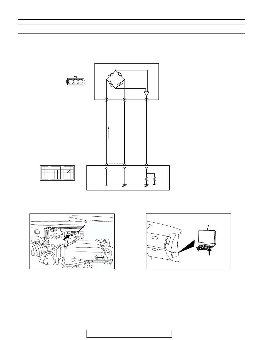
CIRCUIT OPERATION
• A 5-volt voltage is applied on the manifold differ-
ential pressure sensor power terminal (terminal
No. 3) from the PCM (terminal No. 106). The
ground terminal (terminal No. 2) is grounded with
the PCM (terminal No. 105).
• A voltage proportional to the pressure in the
intake manifold plenum is sent from the manifold
differential pressure sensor output terminal (ter-
minal No. 1) to the PCM (terminal No. 101).
.
BLA
CK
GREEN-YELLO
W
BLUE-YELLO
W
AK201150
2
1
3
5 V
101
POWERTRAIN CONTROL MODULE (PCM)
2 3
1
B-28
(MU802723)
96
97
MANIFOLD DIFFERENTIAL
PRESSURE SENSOR
Manifold Differential Pressure Sensor Circuit
9192
939495
96979899
100
105
113114
115116117
118119120
106
107108109
110111112
101102103
104
D-135
(MU803805)
AK200974
MANIFOLD
DIFFERENTIAL
PRESSURE
SENSOR
AB
B-28(B)
CONNECTOR: B-28
AK201038AF
CONNECTOR: D-135
PCM
D-135(GR)