Mitsubishi Montero (2002-2004). Manual - part 683


  Index      Mitsubishi     Mitsubishi Montero - service repair manual 2002-2004 year


Search            


Content   ..  681  682  683  684   ..


Mitsubishi Montero (2002-2004). Manual - part 683


TSB Revision

DIAGNOSTIC TROUBLE CODE PROCEDURES

13Ac-429

DTC SET CONDITIONS

Check Conditions

• Engine is being cranked.

• Battery positive voltage is at between 10 and 16 

volts.

Judgment Criteria

• The evaporative emission ventilation solenoid 

coil surge voltage (battery positive voltage + 2 
volts) is not detected for 0.2 second.

• The PCM monitors for this condition once during 

the drive cycle.

Check Conditions

• Battery positive voltage is at between 10 and 16 

volts.

• ON duty cycle of the evaporative emission purge 

solenoid is 0 percent.

• Evaporative emission ventilation solenoid is ON.

• More than 1 second has elapsed after the above 

mentioned conditions have been met. 

Judgment Criteria

• The evaporative emission ventilation solenoid 

coil surge voltage (battery positive voltage + 2 
volts) is not detected for 1 second. When the 
evaporative emission ventilation solenoid is 
turned OFF.

.

TROUBLESHOOTING HINTS (The most likely 
causes for this code to be set are: )

• Evaporative emission ventilation solenoid failed.

• Open or shorted evaporative emission ventilation 

solenoid circuit, or loose connector.

• PCM failed. 

DIAGNOSIS

Required Special Tool:

• MB991502: Scan Tool (MUT-II)

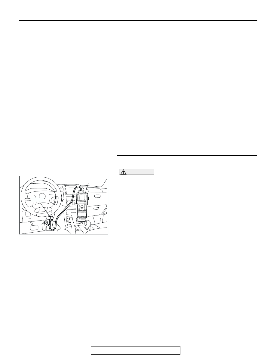
STEP 1. Using scan tool MB991502, check actuator test 
item 29: Evaporative Emission Ventilation Solenoid.

CAUTION

To prevent damage to scan tool MB991502, always turn the 
ignition switch to the "LOCK" (OFF) position before con-
necting or disconnecting scan tool MB991502.
(1) Connect scan tool MB991502 to the data link connector.
(2) Turn the ignition switch to the "ON" position.
(3) Set scan tool MB991502 to the actuator test mode for item 

29, Evaporative emission ventilation solenoid.

• An operation sound should be heard and vibration 

should be felt when the evaporative emission ventilation 
solenoid is operated.

(4) Turn the ignition switch to the "LOCK" (OFF) position.
Q: Is the solenoid operating properly?

YES : It can be assumed that this malfunction is intermittent. 

Refer to GROUP 00, How to Use Troubleshooting/
Inspection Service Points 

P.00-6

.

NO :  Go to Step 2.

ACX01539

16-PIN

MB991502

AC

TSB Revision

DIAGNOSTIC TROUBLE CODE PROCEDURES

13Ac-430

STEP 2. Check connector G-27 at the evaporative emission 
ventilation solenoid for damage.
Q: Is the connector in good condition?

YES : Go to Step 3.
NO :  Repair or replace it. Refer to GROUP 00E, Harness 

Connector Inspection 

P.00E-2

. Then go to Step 12.

STEP 3. Check the evaporative emission ventilation 
solenoid.
(1) Disconnect the evaporative emission ventilation solenoid 

connector G-27.

(2) Measure the resistance between evaporative emission 

ventilation solenoid side connector terminal No. 1 and No. 
2.

Standard value: 17 

 21 ohms [at 20°C (68°F)]

Q: Is the resistance between 17 and 21 ohms [at 20

°

(68

°F)]?

YES : Go to Step 4.
NO :  Replace the over vent valve module. Then go to Step 

12.

AK200969

1

2

G-27(B)

AB

CONNECTOR: G-27

HARNESS 
CONNECTOR: 
COMPONENT SIDE

AK200969

1

2

G-27(B)

AB

CONNECTOR: G-27

HARNESS 
CONNECTOR: 
COMPONENT SIDE

AK000004

2

1

EVAPORATIVE EMISSION
VENTILATION SOLENOID

AB

TSB Revision

DIAGNOSTIC TROUBLE CODE PROCEDURES

13Ac-431

STEP 4. Measure the power supply voltage at evaporative 
emission ventilation solenoid harness side connector G-
27.
(1) Disconnect the connector G-27 and measure at the harness 

side.

(2) Turn the ignition switch to the "ON" position.

(3) Measure the voltage between terminal No. 2 and ground.

• Voltage should be battery positive voltage.

(4) Turn the ignition switch to the "LOCK" (OFF) position.
Q: Is battery positive voltage (approximately 12 volts) 

present?
YES : 
Go to Step 6.
NO :  Go to Step 5.

STEP 5. Check connector B-22X at MFI relay for damage.
Q: Is the connector in good condition?

YES : Check connectors D-116, E-111, D-112 and F-10 at 

intermediate connector for damage, and repair or 
replace as required. Refer to GROUP 00E, Harness 
Connector Inspection 

P.00E-2

. If intermediate 

connectors are in good condition, repair harness wire 
between MFI relay connector B-22X (terminal No. 1) 
and evaporative emission ventilation solenoid 
connector G-27 (terminal No. 2) because of open 
circuit or short circuit to ground. Then go to Step 12.

NO :  Repair or replace it. Refer to GROUP 00E, Harness 

Connector Inspection 

P.00E-2

. Then go to Step 12.

AK200969

1

2

G-27(B)

AB

CONNECTOR: G-27

HARNESS 
CONNECTOR: 
COMPONENT SIDE

AKX01502

G-27 HARNESS 
CONNECTOR: 
COMPONENT SIDE

1

AW

2

AK200951

2 1

3

4

B-22X

AB

CONNECTOR: B-22X

HARNESS 
CONNECTOR: 
COMPONENT SIDE

TSB Revision

DIAGNOSTIC TROUBLE CODE PROCEDURES

13Ac-432

STEP 6. Measure the power supply voltage at PCM 
connector D-132 by backprobing.
(1) Do not disconnect the connector D-132.
(2) Turn the ignition switch to the "ON" position.

(3) Measure the voltage between terminal No. 11 and ground 

by backprobing.

• Voltage should be battery positive voltage.

(4) Turn the ignition switch to the "LOCK" (OFF) position.
Q: Is battery positive voltage (approximately 12 volts) 

present?
YES : 
Go to Step 9.
NO :  Go to Step 7.

STEP 7. Check connector D-132 at PCM for damage.
Q: Is the connector in good condition?

YES : Go to Step 8.
NO :  Repair or replace it. Refer to GROUP 00E, Harness 

Connector Inspection 

P.00E-2

. Then go to Step 12.

AK200938

2

3

4

5

6

7

8

9

1

10

14

15

16

17

18

19

20

21

22

23

24

25

26

27

11

12

13

AB

CONNECTOR: D-132

HARNESS CONNECTOR: 
COMPONENT SIDE

PCM

D-132(GR)

AK201422

1

2

3

5

6 7 8 9

4

20

21 22

232425

2627

10111213

14 15

16 1718

19

AB

D-132 HARNESS 
CONNECTOR: 
HARNESS SIDE

AK200938

2

3

4

5

6

7

8

9

1

10

14

15

16

17

18

19

20

21

22

23

24

25

26

27

11

12

13

AB

CONNECTOR: D-132

HARNESS CONNECTOR: 
COMPONENT SIDE

PCM

D-132(GR)


Content   ..  681  682  683  684   ..