Mitsubishi Montero (2002-2004). Manual - part 670


  Index      Mitsubishi     Mitsubishi Montero - service repair manual 2002-2004 year


Search            


Content   ..  668  669  670  671   ..


Mitsubishi Montero (2002-2004). Manual - part 670


TSB Revision

DIAGNOSTIC TROUBLE CODE PROCEDURES

13Ac-377

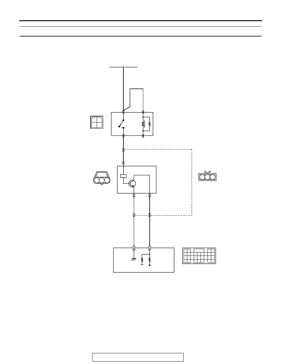
DTC P0340: Camshaft Position Sensor Circuit

WHITE-

BLA

CK

WHITE-

BLA

CK

AK201143

RED

RED

BLA

CK-

WHITE

BLUE

BLUE

MFI RELAY

BATTERY

71

3

2

1

3 4

1 2

B-22X

5V

POWERTRAIN
CONTROL
MODULE (PCM)

3

1 2

B-10

MU802337

2

1

4

CAMSHAFT
POSITION
SENSOR

3

3

1

2

2 3

1

B-08

MU802663

Camshaft Position Sensor Circuit

SKY B

ULE

88

61
656667686970 717273
74757677787980 8182
8384

858687

8889

62

6364

D-134

(MU803804)

TSB Revision

DIAGNOSTIC TROUBLE CODE PROCEDURES

13Ac-378

.

CIRCUIT OPERATION

• The camshaft position sensor power is supplied 

from the MFI relay (terminal No. 1).

• Terminal No. 1 of the camshaft position sensor is 

grounded with PCM (terminal No. 88).

• A 5-volt voltage is applied on the camshaft posi-

tion sensor output terminal (terminal No. 2) from 
the PCM (terminal No. 70). The camshaft position 
sensor generates a pulse signal when the output 
terminal is opened and grounded.

.

TECHNICAL DESCRIPTION

• The camshaft position sensor functions to detect 

the top dead center position of the number 1 cyl-
inder and to convert that data to pulse signals 
that are input to the PCM.

• When the engine is running, the camshaft posi-

tion sensor outputs a pulse signal.

• The PCM checks whether pulse signal is input 

while the engine is cranking.

.

DTC SET CONDITIONS

Check Conditions

• Engine speed is higher than 50 r/min.

Judgment Criteria

• Camshaft position sensor output voltage has not 

changed (no pulse signal is input) for 2 seconds.

Check Conditions

• Engine speed is higher than 50 r/min.

Judgment Criteria

• Normal signal pattern has not been input for cyl-

inder identification from the crankshaft position 
sensor signal and camshaft position sensor sig-
nal for 2 seconds.

.

TROUBLESHOOTING HINTS (The most likely 
causes for this code to be set are: )

• Camshaft position sensor failed.

• Open or shorted camshaft position sensor circuit, 

or loose connector.

• PCM failed.

AK200963

CAMSHAFT POSITION 
SENSOR

AB

B-10(B)

CONNECTOR: B-10

AK201039

MFI RELAY

B-22X

AB

CONNECTOR: B-22X

AK201038

CONNECTOR: D-134

AD

PCM

D-134(GR)

AK201058

B-08(GR)

AB

CONNECTOR: B-08

TSB Revision

DIAGNOSTIC TROUBLE CODE PROCEDURES

13Ac-379

DIAGNOSIS

Required Special Tool:

• MB991709: Test Harness Set

STEP 1. Using the oscilloscope, check the camshaft 
position sensor.
(1) Disconnect the camshaft position sensor connector B-10, 

and connect test harness special tool (MB991709) in 
between. (All terminals should be connected.)

(2) Connect the oscilloscope probe to the camshaft position 

sensor side connector terminal No. 2.
NOTE: When measuring with the PCM side connector, con-
nect an oscilloscope probe to terminal No. 70.

(3) Start the engine and run at idle.
(4) Check the waveform.

• The waveform should show a pattern similar to the illus-

tration.

(5) Turn the ignition switch to the "LOCK" (OFF) position.
Q: Is the waveform normal?

YES : Go to Step 2..
NO :  Go to Step 4.

STEP 2. Check connector B-10 at camshaft position 
sensor for damage.
Q: Is the connector in good condition?

YES : Go to Step 3.
NO :  Repair or replace it. Refer to GROUP 00E, Harness 

Connector Inspection 

P.00E-2

. Then go to Step 20.

AK200965

1

2

3

AB

B-10(B)

CONNECTOR: B-10

HARNESS 
CONNECTOR: 
COMPONENT SIDE

AK102976AB

1 2 3

CAMSHAFT POSITION
SENSOR CONNECTOR

OSCILLOSCOPE

MB991709

AKX01420AB

2 ENGINE REVOLUTIONS

NORMAL WAVEFORM

5V

AK200965

1

2

3

AB

B-10(B)

CONNECTOR: B-10

HARNESS 
CONNECTOR: 
COMPONENT SIDE

TSB Revision

DIAGNOSTIC TROUBLE CODE PROCEDURES

13Ac-380

STEP 3. Check the trouble symptoms.
(1) Carry out a test drive with the drive cycle pattern. Refer to 

GROUP 13A, Trouble Code Diagnosis 

− OBD-II Drive Cycle 

− Procedure 6 − Other Monitor 

P.13Ab-2

.

(2) Check the diagnostic trouble code (DTC).
Q: Is DTC P0340 set?

YES : Replace the PCM. Then go to Step 20.
NO :  It can be assumed that this malfunction is intermittent. 

Refer to GROUP 00, How to Use Troubleshooting/
Inspection Service Points 

P.00-6

.

STEP 4. Check connector B-10 at camshaft position 
sensor for damage.
Q: Is the connector in good condition?

YES : Go to Step 5.
NO :  Repair or replace it. Refer to GROUP 00E, Harness 

Connector Inspection 

P.00E-2

. Then go to Step 20.

STEP 5. Measure the sensor supply voltage at camshaft 
position sensor connector B-10.
(1) Disconnect the connector B-10 and measure at the harness 

side.

(2) Turn the ignition switch to the "ON" position.

(3) Measure the voltage between terminal No. 2 and ground.

• Voltage should be between 4.8 and 5.2 volts.

(4) Turn the ignition switch to the "LOCK" (OFF) position.
Q: Is the measured voltage between 4.8 and 5.2 volts?

YES : Go to Step 10.
NO :  Go to Step 6.

AK200965

1

2

3

AB

B-10(B)

CONNECTOR: B-10

HARNESS 
CONNECTOR: 
COMPONENT SIDE

AK200965

1

2

3

AB

B-10(B)

CONNECTOR: B-10

HARNESS 
CONNECTOR: 
COMPONENT SIDE

AKX01421

B-10 HERNESS 
CONNECTOR: 
COMPONENT SIDE

1

2

3

AJ


Content   ..  668  669  670  671   ..