Mitsubishi Montero (2002-2004). Manual - part 662


  Index      Mitsubishi     Mitsubishi Montero - service repair manual 2002-2004 year


Search            


Content   ..  660  661  662  663   ..


Mitsubishi Montero (2002-2004). Manual - part 662


TSB Revision

DIAGNOSTIC TROUBLE CODE PROCEDURES

13Ac-345

DIAGNOSIS

Required Special Tool:

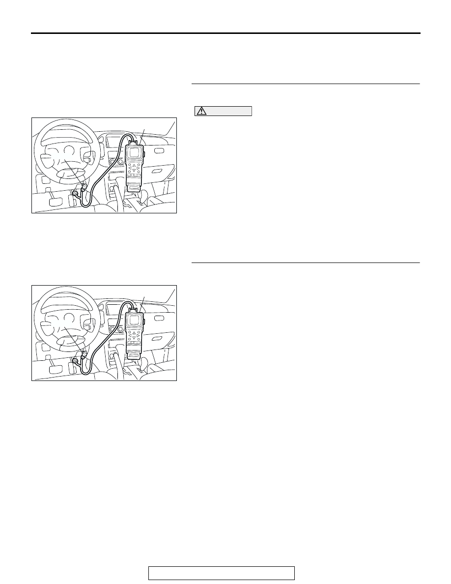
• MB991502: Scan Tool (MUT-II)

STEP 1. Using scan tool MB991502, check data list item 22: 
Crankshaft Position Sensor.

CAUTION

To prevent damage to scan tool MB991502, always turn the 
ignition switch to the "LOCK" (OFF) position before con-
necting or disconnecting scan tool MB991502.
(1) Connect scan tool MB991502 to the data link connector.
(2) Start the engine and run at idle.
(3) Set scan tool MB991502 to the data reading mode for item 

22, Crankshaft Position Sensor.

(4) Check the waveform of the crankshaft position sensor while 

keeping the engine speed constant.

• The pulse width should be constant.

Q: Is the sensor operating properly?

YES : Go to Step 2.
NO :  Refer to , DTC P0335 

− Crankshaft Position Sensor 

Circuit Malfunction. 

P.13Ac-360

STEP 2. Using scan tool MB991502, check data list item 81 
<bank 1> and 83 <bank2>: Long-Term Fuel Trim.
(1) Start the engine and run at idle.
(2) Set scan tool MB991502 to the data reading mode for item 

81<bank 1> and 83 <bank2>, Long-Term Fuel Trim.

• The fuel trim should be between −12.5 and +12.5 when 

the load is 2,500 r/min (during closed loop) after the 
engine is warmed.

Q: Is the specification normal?

YES : Go to Step 3.
NO :  Refer to, DTC P0171 

− System too Lean (bank 1) 

P.13Ac-273

, DTC P0172 

− System too Rich (bank 1) 

P.13Ac-280

, DTC P0174 

− System too Lean (bank 2) 

P.13Ac-284

, DTC P0175 

− System too Rich (bank 2) 

P.13Ac-291

.

ACX01539

16-PIN

MB991502

AC

ACX01539

16-PIN

MB991502

AC

TSB Revision

DIAGNOSTIC TROUBLE CODE PROCEDURES

13Ac-346

STEP 3. Using scan tool MB991502, check data list item 82 
<bank 1> and 84 <bank2>: Short-Term Fuel Trim.
(1) Start the engine and run at idle.
(2) Set scan tool MB991502 to the data reading mode for item 

82<bank 1> and 84 <bank2>, Short-Term Fuel Trim.

• The fuel trim should be between −12.5 and +12.5 when 

the load is 2,500 r/min (during closed loop) after the 
engine is warmed.

Q: Is the specification normal?

YES : Go to Step 4.
NO :  Refer to, DTC P0171 

− System too Lean (bank 1) 

P.13Ac-273

, DTC P0172 

− System too Rich (bank 1) 

P.13Ac-280

, DTC P0174 

− System too Lean (bank 2) 

P.13Ac-284

, DTC P0175 

− System too Rich (bank 2) 

P.13Ac-291

.

STEP 4. Check the ignition coil spark.
(1) Check each ignition coil spark.
(2) Remove the intake manifold.
(3) Remove the spark plug and connect to the spark plug 

cable.

(4) Ground the spark plug side electrode securely.

• When the engine is cranked, the spark plug should 

spark.

Q: Did it spark?

YES : Go to Step 7.
NO :  Go to Step 5.

STEP 5. Check the spark plugs.

CAUTION

Do not attempt to adjust the gap of the iridium plug. Clean-
ing of the iridium plug may result in damage to the iridium 
and platinum tips. Therefore, if carbon deposits must be 
removed, use a plug cleaner and complete cleaning within 
20 seconds to protect the electrode. Do not use a wire 
brush.
(1) Check the plug gap and replace if the limit is exceeded.

Standard value: 1.0 

 1.1 mm (0.039  0.043 inch)

Limit: 1.3 mm (0.051 inch)

Q: Is the plug gap at the standard value?

YES : Go to Step 6.
NO :  Replace the faulty spark plug. Then go to Step 13.

ACX01539

16-PIN

MB991502

AC

AKX00432

SPARK PLUG

AB

AKX01327AB

IRIDIUM
TIP

PLATINUM
TIP

TSB Revision

DIAGNOSTIC TROUBLE CODE PROCEDURES

13Ac-347

STEP 6. Check the spark plug cable.
(1) Check the cap and coating for cracks.
(2) Measure the resistance.

Limit: maximum 9 kiloohms

Q: Is the resistance normal?

YES : Refer to , INSPECTION PROCEDURE 31 

− Ignition 

Circuit System 

P.13Ad-99

.

NO :  Replace the faulty spark plug cable. Then go to Step 

13.

STEP 7. Check the injector.
(1) Disconnect the injector connector.

(2) Measure the resistance between each injector side 

connector terminal No. 1 and No. 2.

Standard value: 13 

 16 ohms [at 20°C (68°F)]

Q: Is the resistance between 13 and 16 ohms [at 20

°

(68

°F)]?

YES : Go to Step 8.
NO :  Replace the faulty injector. Then go to Step 13.

STEP 8. Check harness connector B-01, B-33, B-02, B-35, 
B-03, B-11 at injector for damage.
Q: Is the harness connector in good condition?

YES : Go to Step 9.
NO :  Repair or replace the faulty injector. Refer to GROUP 

00E, Harness Connector Inspection 

P.00E-2

. Then go 

to Step 13. 

AKX00382

AK200960

1

2

B-03(GR)

B-11(GR)

B-35(GR)

B-33(GR)

B-02(GR)

B-01(GR)

CONNECTORS: B-01, B-02, B-03, B-11, 

B-33, B-35

AB

HARNESS CONNECTOR: 
COMPONENT SIDE

AKX01414AB

INJECTOR SIDE
CONNECTOR

1 2

AK200960

1

2

B-03(GR)

B-11(GR)

B-35(GR)

B-33(GR)

B-02(GR)

B-01(GR)

CONNECTORS: B-01, B-02, B-03, B-11, 

B-33, B-35

AB

HARNESS CONNECTOR: 
COMPONENT SIDE

TSB Revision

DIAGNOSTIC TROUBLE CODE PROCEDURES

13Ac-348

STEP 9. Check harness connector D-132 at PCM for 
damage.
Q: Is the harness connector in good condition?

YES : Go to Step 10.
NO :  Repair or replace it. Refer to GROUP 00E, Harness 

Connector Inspection 

P.00E-2

. Then go to Step 13.

STEP 10. Check for harness damage between injector 
connector and PCM connector.

a. Check the harness wire between injector connector B-01 

(terminal No. 2) and PCM connector D-132 (terminal No. 1) 
when checking No. 1 cylinder injector.

b. Check the harness wire between injector connector B-33 

(terminal No. 2) and PCM connector D-132 (terminal No. 5) 
when checking No. 2 cylinder injector.

c. Check the harness wire between injector connector B-02 

(terminal No. 2) and PCM connector D-132 (terminal No. 
14) when checking No. 3 cylinder injector.

d. Check the harness wire between injector connector B-35 

(terminal No. 2) and PCM connector D-132 (terminal No. 
21) when checking No. 4 cylinder injector.

e. Check the harness wire between injector connector B-03 

(terminal No. 2) and PCM connector D-132 (terminal No. 2) 
when checking No. 5 cylinder injector.

f. Check the harness wire between injector connector B-11 

(terminal No. 2) and PCM connector D-132 (terminal No. 6) 
when checking No. 6 cylinder injector.

Q: Is the harness wire in good condition?

YES : Go to Step 11.
NO :  Repair it. Then go to Step 13.

AK200938

2

3

4

5

6

7

8

9

1

10

14

15

16

17

18

19

20

21

22

23

24

25

26

27

11

12

13

AB

CONNECTOR: D-132

HARNESS CONNECTOR: 
COMPONENT SIDE

PCM

D-132(GR)

AK200960

1

2

B-03(GR)

B-11(GR)

B-35(GR)

B-33(GR)

B-02(GR)

B-01(GR)

CONNECTORS: B-01, B-02, B-03, B-11, 

B-33, B-35

AB

HARNESS CONNECTOR: 
COMPONENT SIDE

AK200938

2

3

4

5

6

7

8

9

1

10

14

15

16

17

18

19

20

21

22

23

24

25

26

27

11

12

13

AB

CONNECTOR: D-132

HARNESS CONNECTOR: 
COMPONENT SIDE

PCM

D-132(GR)


Content   ..  660  661  662  663   ..