Mitsubishi Montero (2002-2004). Manual - part 661


  Index      Mitsubishi     Mitsubishi Montero - service repair manual 2002-2004 year


Search            


Content   ..  659  660  661  662   ..


Mitsubishi Montero (2002-2004). Manual - part 661


TSB Revision

DIAGNOSTIC TROUBLE CODE PROCEDURES

13Ac-341

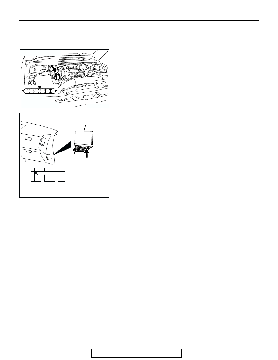
STEP 5. Check for open circuit and harness damage 
between throttle position sensor connector B-05 (terminal 
No. 4) and PCM connector D-135 (terminal No. 105).
Q: Is the harness wire in good condition?

YES : Go to Step 6.
NO :  Repair it. Then go to Step 9.

AK201174

1

6 5 4 3 2

B-05(B)

CONNECTOR: B-05

HARNESS 
CONNECTOR: 
COMPONENT SIDE

AB

AK200947

91

92

93

94

95

96

97

98

99

100

101

102

103

104

105

106

107

108

109

110

111

112

113

114

115

116

117

118

119

120

CONNECTOR: D-135

HARNESS CONNECTOR: 
COMPONENT SIDE

AB

PCM

D-135(GR)

TSB Revision

DIAGNOSTIC TROUBLE CODE PROCEDURES

13Ac-342

STEP 6. Using scan tool MB991502, check data list item 14: 
Throttle Position Sensor (sub).

CAUTION

To prevent damage to scan tool MB991502, always turn the 
ignition switch to the "LOCK"(OFF) position before con-
necting or disconnecting scan tool MB991502
(1) Connect scan tool MB991502 to the data link connector.
(2) Turn the ignition switch to the "ON" position.
(3) Detach the intake air hose at the throttle body.
(4) Disconnect the connector of the throttle position sensor.
(5) Use test harness special tool (MB991348) to connect only 

terminals No. 1, No. 2, No. 3, and No. 4.

(6) Set scan tool MB991502 to the data reading mode for item 

14, Throttle Position Sensor (sub).

• Output voltage should be between 2.2 and 2.8 volts 

when the throttle valve is fully closed with your finger.

• Output voltage should be between 3.8 and 4.9 volts 

when the throttle valve is fully open with your finger.

(7) Turn the ignition switch to the "LOCK"(OFF) position.
Q: Is the sensor operating properly?

YES : It can be assumed that this malfunction is intermittent. 

Refer to GROUP 00, How to Use Troubleshooting/
Inspection Service Points 

P.00-6

.

NO :  Replace the PCM. Then go to Step 9.

STEP 7. Check the throttle position sensor.
(1) Disconnect the connector B-05.

(2) Measure the resistance between throttle position sensor 

side connector terminal No. 2 and No. 4.

Standard value: 2 

 4 kiloohms

Q: Is the measured resistance between 2 and 4 kiloohms?

YES : Go to Step 8.
NO :  Replace the throttle body ASSY. Then go to Step 9.

ACX01539

16-PIN

MB991502

AC

AK201174

1

6 5 4 3 2

B-05(B)

CONNECTOR: B-05

HARNESS 
CONNECTOR: 
COMPONENT SIDE

AB

6

1 2 3 4 5

AK201512

THROTTLE POSITION
SENSOR SIDE 
CONNECTOR

AB

TSB Revision

DIAGNOSTIC TROUBLE CODE PROCEDURES

13Ac-343

STEP 8. Using scan tool MB991502, check data list item 14: 
Throttle Position Sensor (sub).

CAUTION

To prevent damage to scan tool MB991502, always turn the  
ignition switch to the "LOCK"(OFF) position before con-
necting or  disconnecting scan tool MB991502.
(1) Connect scan tool MB991502 to the data link connector.
(2) Turn the ignition switch to the "ON" position.
(3) Detach the intake air hose at the throttle body.
(4) Disconnect the connector of the throttle position sensor.
(5) Use test harness special tool (MB991348) to connect only 

terminals No. 1, No. 2, No. 3, and No. 4.

(6) Set scan tool MB991502 to the data reading mode for item 

14, Throttle Position Sensor (sub).

• Output voltage should be between 2.2 and 2.8 volts 

when the throttle valve is fully closed with your finger.

• Output voltage should be between 3.8 and 4.9 volts 

when the throttle valve is fully open with your finger.

(7) Turn the ignition switch to the "LOCK"(OFF) position.
Q: Is the sensor operating properly?

YES : It can be assumed that this malfunction is intermittent. 

Refer to GROUP 00, How to Use Troubleshooting/
Inspection Service Points 

P.00-6

.

NO :  Replace the PCM. Then go to Step 9.

STEP 9. Using scan tool MB991502, read the diagnostic 
trouble code (DTC).
(1) Connect scan tool MB991502 to the data link connector.
(2) Turn the ignition switch to the "ON" position.
(3) After the DTC has been deleted, read the DTC again.
(4) Turn the ignition switch to the "LOCK"(OFF) position.
Q: Is DTC P0223 set?

YES : Retry the troubleshooting.
NO :  The inspection is complete.

ACX01539

16-PIN

MB991502

AC

ACX01539

16-PIN

MB991502

AC

TSB Revision

DIAGNOSTIC TROUBLE CODE PROCEDURES

13Ac-344

DTC P0300: Random/Multiple Cylinder Misfire Detected 

.

Random Misfire Circuit

• Refer to DTC P0335 − Crankshaft Position Sen-

sor Circuit. 

P.13Ac-360

• Refer to DTC P0201 − P0206, Injector Circuit. 

P.13Ac-318

.

CIRCUIT OPERATION

• Refer to DTC P0335 − Crankshaft Position Sen-

sor Circuit. 

P.13Ac-360

• Refer to DTC P0201 − P0206, Injector Circuit. 

P.13Ac-318

.

TECHNICAL DESCRIPTION

• If a misfire occurs while the engine is running, the 

engine speed changes for an instant.

• The PCM checks for such changes in engine 

speed.

.

DTC SET CONDITIONS

Check Conditions

• Engine speed is between 440 and 6,000 r/min.

• Engine coolant temperature is higher than −10°C 

(14

°F).

• Intake air temperature is higher than −10°C 

(14

°F).

• Barometric pressure is higher than 76 kPa (11 

psi).

• Volumetric efficiency is at between 30 and 60 

percent.

• Adaptive learning is complete for the vane which 

generates a crankshaft position signal.

• While the engine is running, excluding gear shift-

ing, deceleration, sudden acceleration/decelera-
tion and A/C compressor switching. Judgement 
Criteria (change in the angular acceleration of the 
crankshaft is used for misfire detection).

• The throttle deviation is −0.059 V/10 ms to 

+0.059 V/10 ms.

Judgement Criteria (change in the angular accel-

eration of the crankshaft is used for misfire 
detection).

• Misfire has occurred more frequently than 

allowed during  the last 200 revolutions [when the 
catalyst temperature is higher than 950

°C 

(1742

°F)].

or

• Misfire has occurred in 20 or more of the last 

1,000 revolutions (corresponding to 1.5 times the 
limit of emission standard).

.

TROUBLESHOOTING HINTS (The most likely 
causes for this code to be set are: )

• Ignition system related part(s) failed.

• Poor crankshaft position sensor.

• Incorrect air/fuel ratio.

• Low compression pressure.

• Skipping of timing belt teeth.

• EGR system and EGR valve failed.

• PCM failed.


Content   ..  659  660  661  662   ..