Mitsubishi Montero (2002-2004). Manual - part 651


  Index      Mitsubishi     Mitsubishi Montero - service repair manual 2002-2004 year


Search            


Content   ..  649  650  651  652   ..


Mitsubishi Montero (2002-2004). Manual - part 651


TSB Revision

DIAGNOSTIC TROUBLE CODE PROCEDURES

13Ac-301

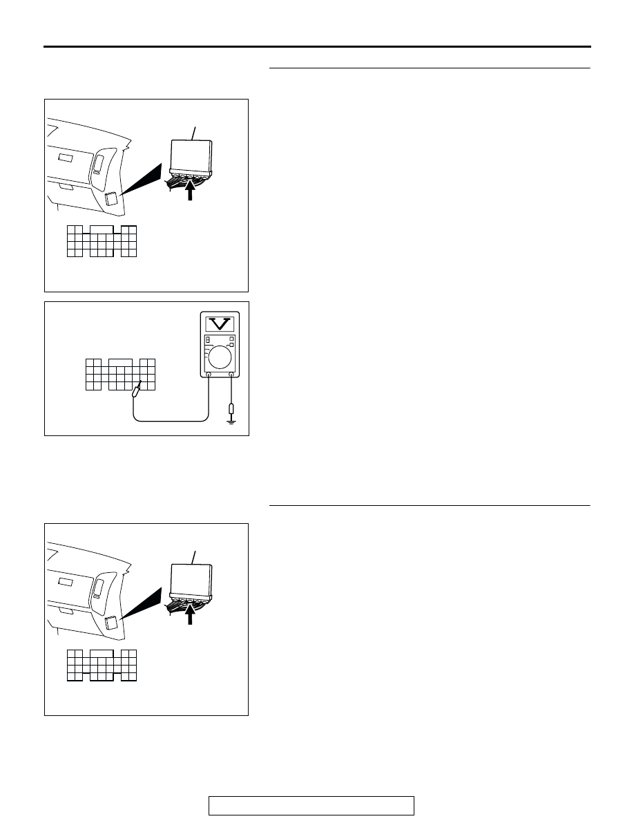
STEP 6. Measure the sensor supply voltage at PCM 
connector D-134 by backprobing.
(1) Do not disconnect the PCM connector D-134.
(2) Turn the ignition switch to the "ON" position.

(3) Measure the voltage between terminal No. 81 and ground 

by backprobing.

• When fuel tank temperature is 0°C (32°F), voltage 

should be 2.7 and 3.1 volts.

• When fuel tank temperature is 20°C (68°F), voltage 

should be 2.1 and 2.5 volts.

• When fuel tank temperature is 40°C (104°F), voltage 

should be 1.6 and 2.0 volts.

• When fuel tank temperature is 80°C (176°F), voltage 

should be 0.8 and 1.2 volts.

(4) Turn the ignition switch to the "LOCK" (OFF) position.
Q: Is the voltage normal?

YES : Go to Step 7.
NO :  Go to Step 8.

STEP 7. Check connector D-134 at PCM for damage.
Q: Is the connector in good condition?

YES :  Check connector D-111 and F-07 at intermediate 

connector for damage, and repair or replace as 
required. Refer to GROUP 00E, Harness Connector 
Inspection 

P.00E-2

If intermediate connector are in 

good condition, repair harness wire between fuel level 
sensor connector G-03 (terminal No. 3) and PCM 
connector D-134 (terminal No. 81) because of open 
circuit. Then go to Step 12.

NO :  Repair or replace it. Refer to GROUP 00E, Harness 

Connector Inspection 

P.00E-2

. Then go to Step 12.

AK201166

61

62

63

64

65

66

67

68

69

70

71

76

77

78

79

85

86

87

80

72

73

74

75

81

82

83

84

88

89

CONNECTOR: D-134

AB

PCM

D-134(GR)

HARNESS CONNECTOR: 
COMPONENT SIDE

AK201414

61
656667686970 717273
74757677787980 8182
8384

858687

8889

62

6364

D-134 HARNESS 
CONNECTOR: 
HARNESS SIDE

AB

AK201166

61

62

63

64

65

66

67

68

69

70

71

76

77

78

79

85

86

87

80

72

73

74

75

81

82

83

84

88

89

CONNECTOR: D-134

AB

PCM

D-134(GR)

HARNESS CONNECTOR: 
COMPONENT SIDE

TSB Revision

DIAGNOSTIC TROUBLE CODE PROCEDURES

13Ac-302

STEP 8. Check connector D-134 at PCM for damage.
Q: Is the connector in good condition?

YES : Go to Step 9.
NO :  Repair or replace it. Refer to GROUP 00E, Harness 

Connector Inspection 

P.00E-2

. Then go to Step 12.

STEP 9. Check for short circuit to ground between fuel 
level sensor connector G-03 (terminal No. 3) and PCM 
connector D-134 (terminal No. 81).
Q: Is the harness wire in good condition?

YES : Replace the PCM. Then go to Step 12.
NO :  Repair it. Then go to Step 12.

AK201166

61

62

63

64

65

66

67

68

69

70

71

76

77

78

79

85

86

87

80

72

73

74

75

81

82

83

84

88

89

CONNECTOR: D-134

AB

PCM

D-134(GR)

HARNESS CONNECTOR: 
COMPONENT SIDE

AK200959

1

2

3

AB

CONNECTOR: G-03

G-03(B)

HARNESS 
CONNECTOR: 
COMPONENT SIDE

AK201166

61

62

63

64

65

66

67

68

69

70

71

76

77

78

79

85

86

87

80

72

73

74

75

81

82

83

84

88

89

CONNECTOR: D-134

AB

PCM

D-134(GR)

HARNESS CONNECTOR: 
COMPONENT SIDE

TSB Revision

DIAGNOSTIC TROUBLE CODE PROCEDURES

13Ac-303

STEP 10. Check connector D-134 at PCM for damage.
Q: Is the connector in good condition?

YES : Go to Step 11.
NO :  Repair or replace it. Refer to GROUP 00E, Harness 

Connector Inspection 

P.00E-2

. Then go to Step 12.

STEP 11. Check for harness damage between fuel tank 
temperature sensor connector G-03 (terminal No. 3) and 
PCM connector D-134 (terminal No. 81).
NOTE: Check harness after checking intermediate connector 
D-111, E-113 and F-07. If intermediate connector are damaged, 
repair or replace it. Refer to GROUP 00E, Harness Connector 
Inspection 

P.00E-2

. Then go to Step 12.

Q: Is the harness wire in good condition?

YES : Replace the PCM. Then go to Step 12.
NO :  Repair it. Then go to Step 12.

AK201166

61

62

63

64

65

66

67

68

69

70

71

76

77

78

79

85

86

87

80

72

73

74

75

81

82

83

84

88

89

CONNECTOR: D-134

AB

PCM

D-134(GR)

HARNESS CONNECTOR: 
COMPONENT SIDE

AK200959

1

2

3

AB

CONNECTOR: G-03

G-03(B)

HARNESS 
CONNECTOR: 
COMPONENT SIDE

AK201166

61

62

63

64

65

66

67

68

69

70

71

76

77

78

79

85

86

87

80

72

73

74

75

81

82

83

84

88

89

CONNECTOR: D-134

AB

PCM

D-134(GR)

HARNESS CONNECTOR: 
COMPONENT SIDE

TSB Revision

DIAGNOSTIC TROUBLE CODE PROCEDURES

13Ac-304

STEP 12. Test the OBD-II drive cycle.
(1) Carry out a test drive with the drive cycle pattern. Refer to 

GROUP 13A, Procedure 6 

− Other Monitor 

P.13Ab-2

.

(2) Check the diagnostic trouble code (DTC).
Q: Is DTC P0181 set?

YES : Retry the troubleshooting.
NO :  The inspection is complete.


Content   ..  649  650  651  652   ..