Mitsubishi Montero (2002-2004). Manual - part 649


  Index      Mitsubishi     Mitsubishi Montero - service repair manual 2002-2004 year


Search            


Content   ..  647  648  649  650   ..


Mitsubishi Montero (2002-2004). Manual - part 649


TSB Revision

DIAGNOSTIC TROUBLE CODE PROCEDURES

13Ac-293

STEP 3. Using scan tool MB991502, check data list item 21: 
Engine Coolant Temperature Sensor.
(1) Turn the ignition switch to the "ON" position.
(2) Set scan tool MB991502 to the data reading mode for item 

21, Engine Coolant Temperature Sensor.

• The engine coolant temperature and temperature 

shown with the scan tool should approximately match.

(3) Turn the ignition switch to the "LOCK" (OFF) position.
Q: Is the sensor operating properly?

YES : Go to Step 4.
NO :  Refer to , DTC P0116 

− Engine Coolant Temperature 

Circuit Range/Performance Problem 

P.13Ac-60

, DTC 

P0117 

− Engine Coolant Temperature Circuit Low 

Input 

P.13Ac-70

, DTC P0118 

− Engine Coolant 

Temperature Circuit High Input 

P.13Ac-74

.

STEP 4. Using scan tool MB991502, check data list item 25: 
Barometric Pressure Sensor.
(1) Turn the ignition switch to the "ON" position.
(2) Set scan tool MB991502 to the data reading mode for item 

25, Barometric Pressure Sensor.

• When altitude is 0 m (0 foot), 101 kPa (29.8 in.Hg.).

• When altitude is 600 m (1,969 feet), 95 kPa (28.1  

in.Hg.).

• When altitude is 1,200 m (3,937 feet), 88 kPa (26.0 

in.Hg.).

• When altitude is 1,800 m (5,906 feet), 81 kPa. (23.9 

in.Hg.)

(3) Turn the ignition switch to the "LOCK" (OFF) position.
Q: Is the sensor operating properly?

YES : Go to Step 5.
NO :  Refer to , DTC P0106 

− Barometric Pressure Circuit 

Range/Performance Problem 

P.13Ac-17

,  DTC 

P0107 

− Barometric Pressure Temperature Circuit 

Low Input 

P.13Ac-22

, DTC P0108 

− Barometric 

Pressure Temperature Circuit High Inpu

P.13Ac-35

.

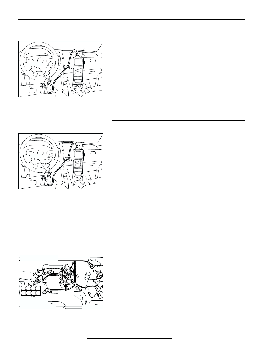
STEP 5. Check harness connector B-44 at injector 
intermediate connector for damage.
Q: Is the harness connector in good condition?

YES : Go to Step 6.
NO :  Repair or replace it. Refer to GROUP 00E, Harness 

Connector Inspection 

P.00E-2

. Then go to Step 10.

ACX01539

16-PIN

MB991502

AC

ACX01539

16-PIN

MB991502

AC

AK200949

3

4

7

8

1

2

5

6

B-44(B)

CONNECTOR: B-44

AB

HARNESS 
CONNECTOR: 
COMPONENT SIDE

TSB Revision

DIAGNOSTIC TROUBLE CODE PROCEDURES

13Ac-294

STEP 6. Check the left bank injector resistance at 
intermediate connector B-44.
(1) Disconnect the injector intermediate connector B-44.

(2) Measure the resistance between each injector side 

connector terminal.

a. Measure the resistance between terminal No. 8 and No. 

2 when measuring No. 2 cylinder injector.

b. Measure the resistance between terminal No. 8 and No. 

7 when measuring No. 3 cylinder injector.

c. Measure the resistance between terminal No. 8 and No. 

5 when measuring No. 6 cylinder injector.

• Resistance should be between 13 and 16 ohms

[at 20

°C (68°F)].

Q: Is the measured resistance between 13 and 16 ohms [at 

20

°C (68°F)]?

YES : Go to Step 8.
NO :  Go to Step 7.

STEP 7. Check the left bank injector.
(1) Remove the intake manifold.
(2) Disconnect the left bank injector connector, which deviates 

from the standard value at Step 6.

(3) Measure the resistance between injector side connector 

terminal No. 1 and No. 2.

Standard value: 13 

 16 ohms [at 20°C (68°F)]

Q: Is the resistance between 13 and 16 ohms [at 20

°

(68

°F)]?

YES : Repair harness wire between injector intermediate 

connector and left bank injector connector because of 
harness damage. Then go to Step 10.

NO :  Replace the injector. Then go to Step 10.

AK200949

3

4

7

8

1

2

5

6

B-44(B)

CONNECTOR: B-44

AB

HARNESS 
CONNECTOR: 
COMPONENT SIDE

AK000533

6

3 4
7 8

1 2
5

AK000533

6

3 4
7 8

1 2
5

INJECTOR
INTERMEDIATE
CONNECTOR

AB

AK201292

1

2

B-11(GR)

B-35(GR)

B-33(GR)

CONNECTORS: B-11, B-33, B-35

AB

HARNESS 
CONNECTORS: 
COMPONENT SIDE

AKX01414AB

INJECTOR SIDE
CONNECTOR

1 2

TSB Revision

DIAGNOSTIC TROUBLE CODE PROCEDURES

13Ac-295

STEP 8. Check the fuel pressure.
Refer to GROUP 13A, On-vehicle Service 

− Fuel Pressure Test 

P.13Aa-13

.

Q: Are there any abnormalities?

YES : Go to Step 9.
NO :  Repair or replace it. Then go to Step 10.

STEP 9. Replace the left bank injector.
(1) Replace the left bank injector.
(2) Carry out a test drive with the drive cycle pattern. Refer to 

GROUP 13A, Procedure 2 

− Fuel Trim Monitor 

P.13Ab-2

.

(3) Read in the diagnostic trouble code (DTC).
Q: Is DTC P0175 set?

YES : Replace the PCM. Then go to Step 10.
NO :  The inspection is complete.

STEP 10. Test the OBD-II drive cycle.
(1) Carry out a test drive with the drive cycle pattern. Refer to 

GROUP 13A, Procedure 2 

− Fuel Trim Monitor 

P.13Ab-2

.

(2) Check the diagnostic trouble code (DTC).
Q: Is DTC P0175 output?

YES : Retry the troubleshooting.
NO :  The inspection is complete.

AK201292

1

2

B-11(GR)

B-35(GR)

B-33(GR)

CONNECTORS: B-11, B-33, B-35

AB

HARNESS 
CONNECTORS: 
COMPONENT SIDE

TSB Revision

DIAGNOSTIC TROUBLE CODE PROCEDURES

13Ac-296

DTC P0181: Fuel Tank Temperature Sensor Circuit Range/Performance

POWERTRAIN CONTROL
MODULE (PCM)

Fuel Tank Temperature  Sensor  Circuit

2

16

3

2

7

1

BLA

CK

BLA

CK

LIGHT 

GREEN-

RED

G-03

MU802337

1 2 3

AK201139

81

FUEL TANK TEMPERATURE SENSOR
(INTEGRATED IN FUEL LEVEL SENSOR)

4

17

1

12 13 14

18

30

41

34

3

16

10

6 7

19

31

42

20

32

43

21

33

25

24

26

36

35

37

29

28

15

27

38

8 9

39 40

11

2

22

5

23

D-111

8

7

6

5

1 2 3 4

F-07

MU802609

11

1

9 10

13

2

12

3 4

7

5

14

6

8

E-113

5 V

LIGHT 

GREEN-

RED

LIGHT 

GREEN-

RED

LIGHT GREEN-

RED

61
656667686970 717273
74757677787980 8182
8384

858687

8889

62

6364

D-134

(MU803804)


Content   ..  647  648  649  650   ..