Mitsubishi Montero (2002-2004). Manual - part 597
TSB Revision
DIAGNOSTIC TROUBLE CODE PROCEDURES
13Ac-85
STEP 6. Using scan tool MB991502, check data list item 79:
Throttle Position Sensor (main).
CAUTION
To prevent damage to scan tool MB991502, always turn the
ignition switch to the "LOCK"(OFF) position before con-
necting or disconnecting scan tool MB991502.
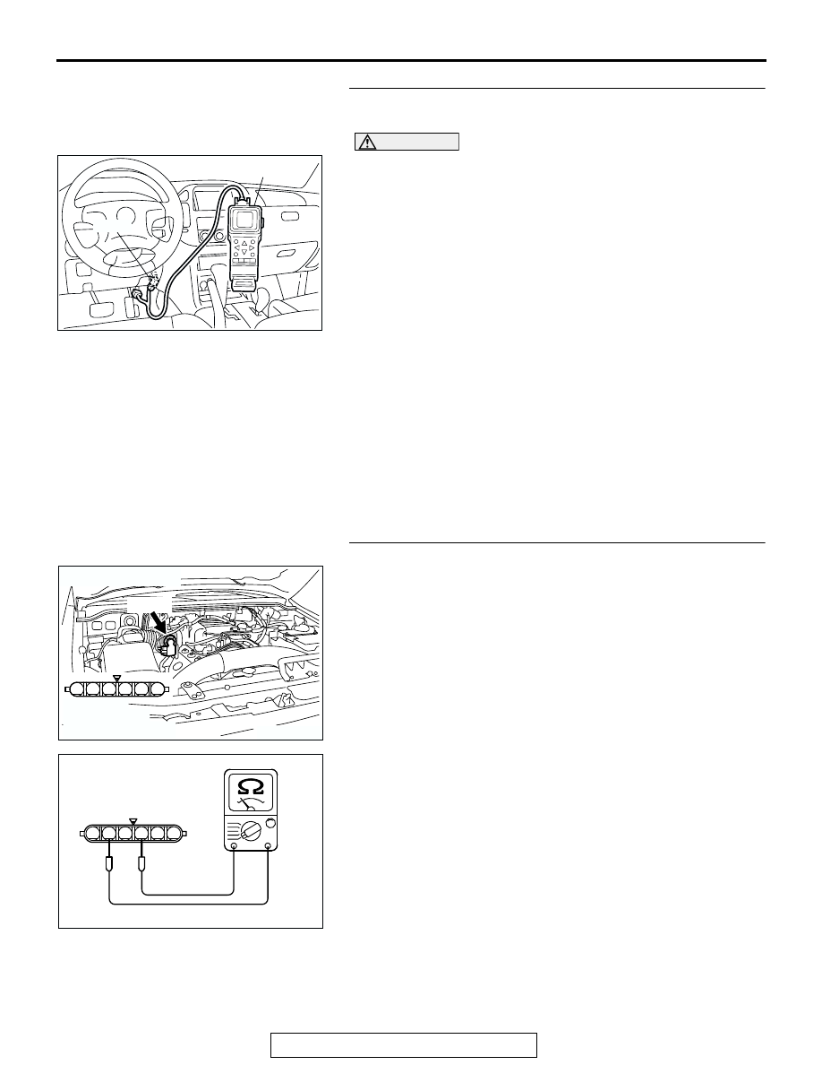
(1) Connect scan tool MB991502 to the data link connector.
(2) Turn the ignition switch to the "ON" position.
(3) Detach the intake air hose at the throttle body.
(4) Disconnect the connector of the throttle position sensor.
(5) Use test harness special tool (MB991348) to connect only
terminals No. 1, No. 2, No. 3, and No. 4.
(6) Set scan tool MB991502 to the data reading mode for
item 79, Throttle Position Sensor (main).
• Output voltage should be between 0.2 and 0.8 volts
when the throttle valve is fully closed with your finger.
• Output voltage should be between 3.8 and 4.9 volts
when the throttle valve is fully open with your finger.
(7) Turn the ignition switch to the "LOCK"(OFF) position.
Q: Is the sensor operating properly?
YES : It can be assumed that this malfunction is intermittent.
Refer to GROUP 00, How to Use Troubleshooting/
Inspection Service Points
NO : Replace the PCM. Then go to Step 12.
STEP 7. Check the throttle position sensor.
(1) Disconnect the connector B-05.
(2) Measure the resistance between throttle position sensor
side connector terminal No. 2 and No. 4.
Standard value: 2
− 4 kiloohms
Q: Is the measured resistance between 2 and 4 kiloohms?
YES : Go to Step 8.
NO : Replace the throttle body ASSY. Then go to Step 12.
ACX01539
16-PIN
MB991502
AC
AK201174
1
6 5 4 3 2
B-05(B)
CONNECTOR: B-05
HARNESS
CONNECTOR:
COMPONENT SIDE
AB
6
1 2 3 4 5
AK201512
THROTTLE POSITION
SENSOR SIDE
CONNECTOR
AB