Mitsubishi Montero (2002-2004). Manual - part 588


  Index      Mitsubishi     Mitsubishi Montero - service repair manual 2002-2004 year


Search            


Content   ..  586  587  588  589   ..


Mitsubishi Montero (2002-2004). Manual - part 588


TSB Revision

DIAGNOSTIC TROUBLE CODE PROCEDURES

13Ac-49

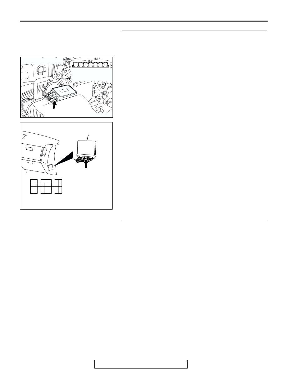
STEP 8. Check for open circuit and harness damage 
between intake air temperature sensor connector B-48 
(terminal No. 5) and PCM connector D-134 (terminal No. 
88).
Q: Is the harness wire in good condition?

YES : Replace the PCM. Then go to Step 9.
NO :  Repair it. Then go to Step 9.

STEP 9. Test the OBD-II drive cycle.
(1) Carry out a test drive with the drive cycle pattern. Refer to 

GROUP 13A, Procedure 6 

− Other Monitor 

P.13Ab-2

.

(2) Check the diagnostic trouble code (DTC).
Q: Is DTC P0111 set?

YES : Retry the troubleshooting.
NO :  The inspection is complete.

AK200937

3

4

5

1

2

6

7

AB

HARNESS 
CONNECTOR: 
COMPONENT SIDE

CONNECTOR: B-48

B-48(B)

AK201166

61

62

63

64

65

66

67

68

69

70

71

76

77

78

79

85

86

87

80

72

73

74

75

81

82

83

84

88

89

CONNECTOR: D-134

AB

PCM

D-134(GR)

HARNESS CONNECTOR: 
COMPONENT SIDE

TSB Revision

DIAGNOSTIC TROUBLE CODE PROCEDURES

13Ac-50

DTC P0112: Intake air temperature Circuit Low Input

.

CIRCUIT OPERATION

• Approximately 5 volts are applied to the intake air 

temperature sensor output terminal (terminal No. 
6) from the PCM (terminal No. 99) via the resistor 
in the PCM. The ground terminal (terminal No. 5) 
is grounded with PCM (terminal No. 88).

• The intake air temperature sensor is a negative 

temperature coefficient type of resistor. When the 
intake air temperature rises, the resistance 
decreases.

• The intake air temperature sensor output voltage 

increases when the resistance increases and 
decreases when the resistance decreases.

.

SKY B

ULE

AK201128

RED-BLUE

INTAKE AIR TEMPERATURE SENSOR
(INCORPORATED IN VOLUME AIRFLOW 
 SENSOR)

POWERTRAIN CONTROL MODULE (PCM)

5 V

99

5

88

6

1 2 3 4 5 6 7

B-48

Intake Air Temperature Sensor Circuit

9192

939495

96979899

100

105

113114

115116117

118119120

106

107108109

110111112

101102103

104

D-135

(MU803805)

61
656667686970 717273
74757677787980 8182
8384

858687

8889

62

6364

D-134

(MU803804)

AK200940AC

CONNECTOR: B-48

INTAKE AIR
TEMPERATURE
SENSOR

B-48(B)

AK201038AK

CONNECTORS: D-134, D-135

PCM

D-134(GR) D-135(GR)

TSB Revision

DIAGNOSTIC TROUBLE CODE PROCEDURES

13Ac-51

TECHNICAL DESCRIPTION

• The intake air temperature sensor converts the 

intake air temperature to a voltage.

• The PCM checks whether this voltage is within a 

specified range.

.

DTC SET CONDITIONS

Check Conditions

• 2 seconds or more have passed since the start-

ing sequence was completed.

Judgement Criteria

• Intake air temperature sensor output voltage has 

continued to be 0.2 volt or lower [corresponding 
to an air intake temperature of 115

°C (239°F) or 

higher] for 2 seconds.

.

TROUBLESHOOTING HINTS (The most likely 
causes for this code to be set are:)

• Intake air temperature sensor failed.

• Open or shorted intake air temperature sensor 

circuit, or loose connector.

• PCM failed.

DIAGNOSIS

Required Special Tool:

• MB991502: Scan Tool (MUT-II)

STEP 1. Using scan tool MB991502, check data list item 13: 
Intake Air Temperature Sensor.

CAUTION

To prevent damage to scan tool MB991502, always turn the 
ignition switch to the "LOCK" (OFF) position before con-
necting or disconnecting scan tool MB991502.
(1) Connect scan tool MB991502 to the data link connector.
(2) Turn the ignition switch to the "ON" position.
(3) Set scan tool MB991502 to the data reading mode for item 

13, Intake Air Temperature Sensor.

• The intake air temperature and temperature shown with 

the scan tool should approximately match.

(4) Turn the ignition switch to the "LOCK" (OFF) position.
Q: Is the sensor operating properly?

YES : It can be assumed that this malfunction is intermittent. 

Refer to GROUP 00, How to Use Troubleshooting/
Inspection Service Points 

P.00-6

.

NO :  Go to Step 2.

STEP 2. Check connector B-48 at the intake air 
temperature sensor for damage.
Q: Is the connector in good condition?

YES : Go to Step 3.
NO :  Repair or replace it. Refer to GROUP 00E, Harness 

Connector Inspection 

P.00E-2

. Then go to Step 6.

ACX01539

16-PIN

MB991502

AC

AK200937

3

4

5

1

2

6

7

AB

HARNESS 
CONNECTOR: 
COMPONENT SIDE

CONNECTOR: B-48

B-48(B)

TSB Revision

DIAGNOSTIC TROUBLE CODE PROCEDURES

13Ac-52

STEP 3. Check the intake air temperature sensor.
(1) Disconnect the intake air temperature sensor connector B-

48.

(2) Measure the resistance between intake air temperature 

sensor side connector terminal No. 5 and No. 6.

• There should be continuity. (0.30 − 1.0 kiloohm)

Q: Is the measured resistance between 0.30 and 1.0 ohms?

YES : Go to Step 4.
NO :  Replace the volume airflow sensor. Then go to Step 6.

STEP 4. Check for short circuit to ground between intake 
air temperature sensor connector B-48 (terminal No.6) and 
PCM connector D-135 (terminal No. 99).
Q: Is the harness wire in good condition?

YES : Go to Step 5.
NO :  Repair it. Then go to Step 6.

AK200937

3

4

5

1

2

6

7

AB

HARNESS 
CONNECTOR: 
COMPONENT SIDE

CONNECTOR: B-48

B-48(B)

AK000319AB

1 2 3 4 5 6 7

INTAKE AIR TEMPERATURE
SENSOR SIDE CONNECTOR

AK200937

3

4

5

1

2

6

7

AB

HARNESS 
CONNECTOR: 
COMPONENT SIDE

CONNECTOR: B-48

B-48(B)

AK200947

91

92

93

94

95

96

97

98

99

100

101

102

103

104

105

106

107

108

109

110

111

112

113

114

115

116

117

118

119

120

CONNECTOR: D-135

HARNESS CONNECTOR: 
COMPONENT SIDE

AB

PCM

D-135(GR)


Content   ..  586  587  588  589   ..