Mitsubishi Montero (2002-2004). Manual - part 586


  Index      Mitsubishi     Mitsubishi Montero - service repair manual 2002-2004 year


Search            


Content   ..  584  585  586  587   ..


Mitsubishi Montero (2002-2004). Manual - part 586


TSB Revision

DIAGNOSTIC TROUBLE CODE PROCEDURES

13Ac-41

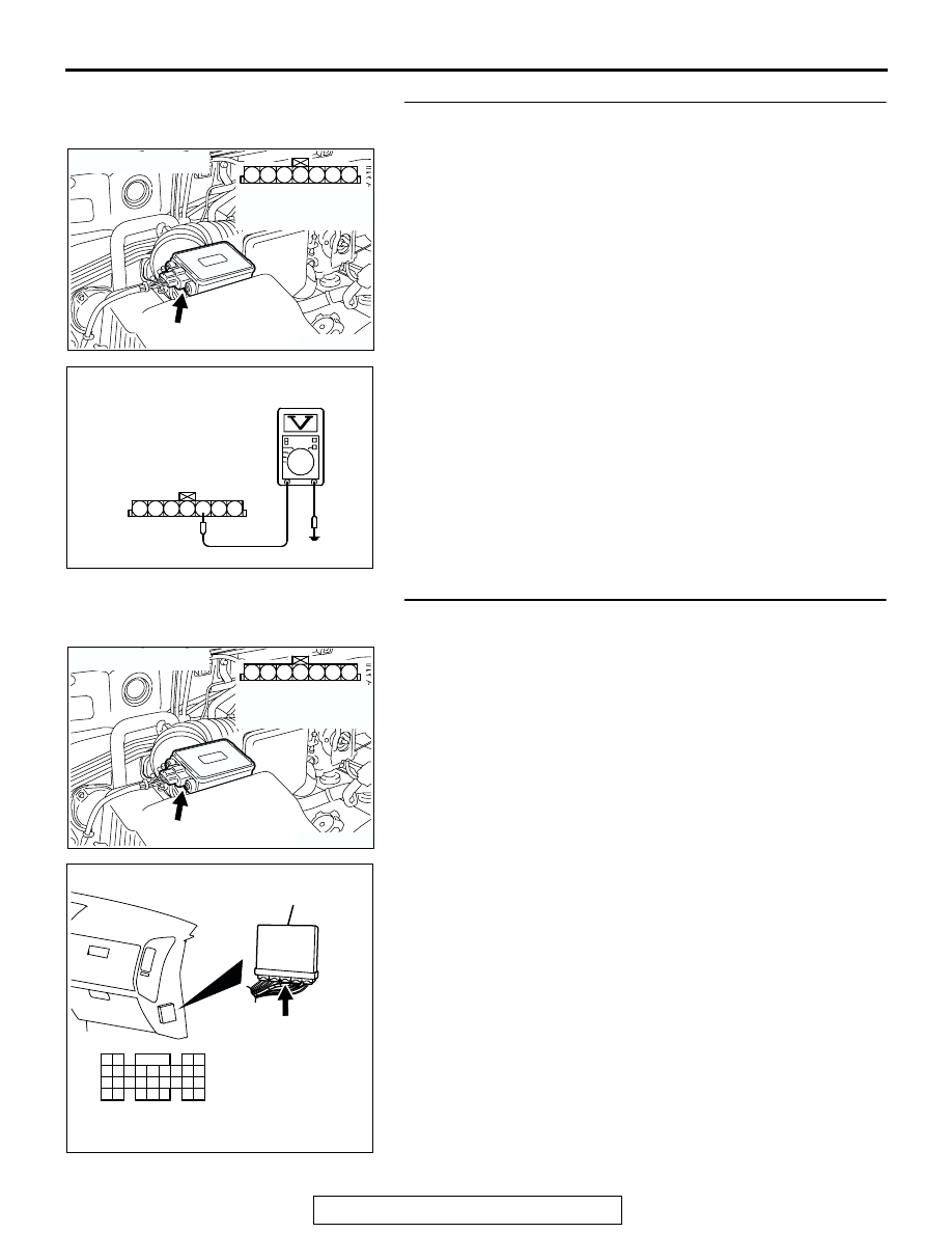
STEP 7. Measure the ground voltage at barometric 
pressure sensor connector B-48 by backprobing.
(1) Do not disconnect the connector B-48.
(2) Turn the ignition switch to the "ON" position.

(3) Measure the voltage between terminal No. 5 and ground by 

backprobing.

• Voltage should be 0.5 volt or less.

(4) Turn the ignition switch to the "LOCK" (OFF) position.
Q: Is the voltage normal?

YES : Go to Step 10.
NO :  Go to Step 8.

STEP 8. Check connector B-48 at the barometric pressure 
sensor and connector D-134 at PCM for damage.
Q: Is the connector in good condition?

YES : Go to Step 9.
NO :  Repair or replace it. Refer to GROUP 00E, Harness 

Connector Inspection 

P.00E-2

. Then go to Step 12.

AK200937

3

4

5

1

2

6

7

AB

HARNESS 
CONNECTOR: 
COMPONENT SIDE

CONNECTOR: B-48

B-48(B)

AKX01517

6 7

1 2 3 4 5

AJ

B-48 HARNESS 
CONNECTOR: 
HARNESS SIDE

AK200937

3

4

5

1

2

6

7

AB

HARNESS 
CONNECTOR: 
COMPONENT SIDE

CONNECTOR: B-48

B-48(B)

AK201166

61

62

63

64

65

66

67

68

69

70

71

76

77

78

79

85

86

87

80

72

73

74

75

81

82

83

84

88

89

CONNECTOR: D-134

AB

PCM

D-134(GR)

HARNESS CONNECTOR: 
COMPONENT SIDE

TSB Revision

DIAGNOSTIC TROUBLE CODE PROCEDURES

13Ac-42

STEP 9. Check for open circuit between barometric 
pressure sensor connector B-48 (terminal No. 5) and PCM 
connector D-134 (terminal No. 88).
Q: Is the harness wire in good condition?

YES : Replace the PCM. Then go to Step 12.
NO :  Repair it. Then go to Step 12.

STEP 10. Check connector B-48 at barometric pressure 
sensor for damage.
Q: Is the connector in good condition?

YES : Go to Step 11.
NO :  Repair or replace it. Refer to GROUP 00E, Harness 

Connector Inspection 

P.00E-2

. Then go to Step 12.

AK200937

3

4

5

1

2

6

7

AB

HARNESS 
CONNECTOR: 
COMPONENT SIDE

CONNECTOR: B-48

B-48(B)

AK201166

61

62

63

64

65

66

67

68

69

70

71

76

77

78

79

85

86

87

80

72

73

74

75

81

82

83

84

88

89

CONNECTOR: D-134

AB

PCM

D-134(GR)

HARNESS CONNECTOR: 
COMPONENT SIDE

AK200937

3

4

5

1

2

6

7

AB

HARNESS 
CONNECTOR: 
COMPONENT SIDE

CONNECTOR: B-48

B-48(B)

TSB Revision

DIAGNOSTIC TROUBLE CODE PROCEDURES

13Ac-43

STEP 11. Check connector D-134 and D-135 at PCM for 
damage.
Q: Is the connector in good condition?

YES : Replace the volume airflow sensor. Then go to Step 

12.

NO :  Repair or replace it. Refer to GROUP 00E, Harness 

Connector Inspection 

P.00E-2

. Then go to Step 12.

STEP 12. Test the OBD-II drive cycle.
(1) Carry out a test drive with the drive cycle pattern. Refer to 

GROUP 13A, Procedure 6 

− Other Monitor 

P.13Ab-2

.

(2) Check the diagnostic trouble code (DTC).
Q: Is DTC P0108 set?

YES : Retry the troubleshooting.
NO :  The inspection is complete.

AK201564

61

62

63

64

65

66

67

68

69

70

71

76

77

78

79

85

86

87

80

72

73

74

75

81

82

83

84

88

89

91

92

93

94

95

96

97

98

99

100

101

102

103

104

105

106

107

108

109

110

111

112

113

114

115

116

117

118

119

120

AB

D-134 HARNESS CONNECTOR: 
COMPONENT SIDE

D-135 HARNESS CONNECTOR: 
COMPONENT SIDE

CONNECTOR: D-134, D-135

PCM

D-134(GR)

D-135(GR)

TSB Revision

DIAGNOSTIC TROUBLE CODE PROCEDURES

13Ac-44

DTC P0111: Intake Air Temperature Circuit Range/Performance Problem

.

CIRCUIT OPERATION

• Approximately 5 volts are applied to the intake air 

temperature sensor output terminal (terminal No. 
6) from the PCM (terminal No. 99) via the resistor 
in the PCM. The ground terminal (terminal No. 5) 
is grounded with PCM (terminal No. 88).

• The intake air temperature sensor is a negative 

temperature coefficient type of resistor. When the 
intake air temperature rises, the resistance 
decreases.

• The intake air temperature sensor output voltage 

increases when the resistance increases and 
decreases when the resistance decreases.

.

SKY B

ULE

AK201128

RED-BLUE

INTAKE AIR TEMPERATURE SENSOR
(INCORPORATED IN VOLUME AIRFLOW 
 SENSOR)

POWERTRAIN CONTROL MODULE (PCM)

5 V

99

5

88

6

1 2 3 4 5 6 7

B-48

Intake Air Temperature Sensor Circuit

9192

939495

96979899

100

105

113114

115116117

118119120

106

107108109

110111112

101102103

104

D-135

(MU803805)

61
656667686970 717273
74757677787980 8182
8384

858687

8889

62

6364

D-134

(MU803804)

AK200940AC

CONNECTOR: B-48

INTAKE AIR
TEMPERATURE
SENSOR

B-48(B)

AK201038AK

CONNECTORS: D-134, D-135

PCM

D-134(GR) D-135(GR)


Content   ..  584  585  586  587   ..