Mitsubishi Montero (2002-2004). Manual - part 580


  Index      Mitsubishi     Mitsubishi Montero - service repair manual 2002-2004 year


Search            


Content   ..  578  579  580  581   ..


Mitsubishi Montero (2002-2004). Manual - part 580


TSB Revision

DIAGNOSTIC TROUBLE CODE PROCEDURES

13Ac-17

STEP 13. Test the OBD-II drive cycle.
(1) Carry out a test drive with the drive cycle pattern. Refer to 

GROUP 13A, Procedure 6 

− Other Monitor 

P.13Ab-2

.

(2) Check the diagnostic trouble code (DTC).
Q: Is DTC P0102 set?

YES : Retry the troubleshooting.
NO :  The inspection is complete.

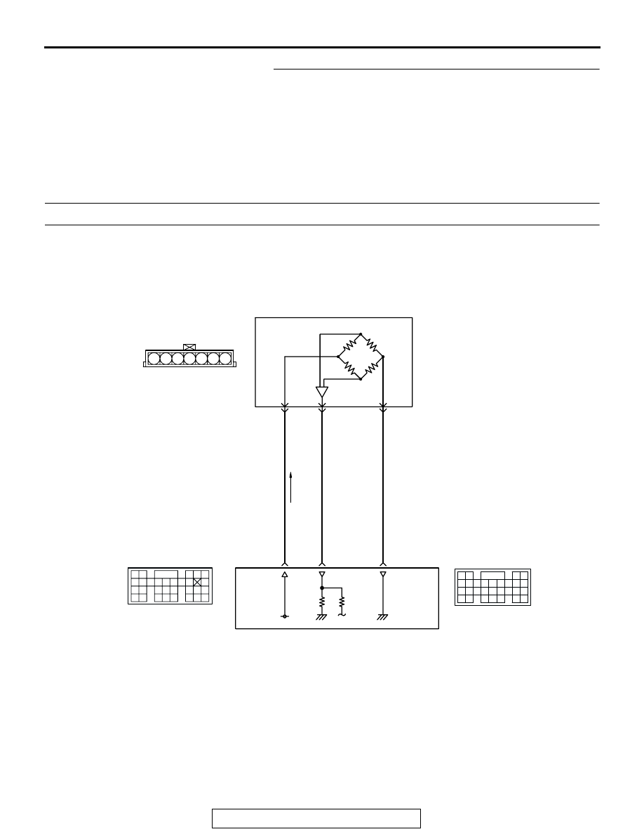
DTC P0106: Barometric Pressure Circuit Range/Performance Problem

AK201127

GREEN-YELLO

W

GREEN-WHITE

SKY B

ULE

BAROMETRIC PRESSURE SENSOR
(INCORPORATED IN VOLUME AIRFLOW 
 SENSOR)

1

97

5 V

100

88

2

5

POWERTRAIN CONTROL MODULE (PCM)

1 2 3 4 5 6 7

B-48

Barometric Pressure Sensor Circuit

9192

939495

96979899

100

105

113114

115116117

118119120

106

107108109

110111112

101102103

104

D-135

(MU803805)

61
656667686970 717273
74757677787980 8182
8384

858687

8889

62

6364

D-134

(MU803804)

TSB Revision

DIAGNOSTIC TROUBLE CODE PROCEDURES

13Ac-18

.

CIRCUIT OPERATION

• A 5-volt voltage is supplied to the barometric 

pressure sensor power terminal (terminal No. 1) 
from the PCM (terminal No. 97). The ground ter-
minal (terminal No. 5) is grounded with PCM (ter-
minal No. 88).

• A voltage that is proportional to the atmospheric 

pressure is sent to the PCM (terminal No. 100) 
from the barometric pressure sensor output ter-
minal (terminal No. 2).

.

TECHNICAL DESCRIPTION

• The barometric pressure sensor outputs a volt-

age which corresponds to the barometric pres-
sure.

• The PCM checks whether this voltage is within a 

specified range.

.

DTC SET CONDITIONS

Check Conditions

• Barometric pressure is lower than 76 kPa (11 

psi).

Judgement Criteria

• During 15 times of driving, the changes in the 

sensor output voltage should be 0.015 volt 
[equivalent to 0.4 kPa (0.06 psi)] or less.

• Make sure that the engine coolant temperature is 

72

°C (160°F) or higher during each of the 15 

times of driving. Also, during each of the 15 times 
of driving, make sure that after the engine has 
been started, the engine coolant temperature has 
increased for 23

°C (40°F) or higher.

.

TROUBLESHOOTING HINTS (The most likely 
causes for this code to be set are:)

• Barometric pressure sensor failed.

• Open or shorted barometric pressure sensor cir-

cuit, or loose connector.

• PCM failed.

DIAGNOSIS

Required Special Tool:

• MB991502: Scan Tool (MUT-II)

STEP 1. Using scan tool MB991502, read the diagnostic 
trouble code (DTC).

CAUTION

To prevent damage to scan tool MB991502, always turn the 
ignition switch to the "LOCK" (OFF) position before con-
necting or disconnecting scan tool MB991502.
(1) Connect scan tool MB991502 to the data link connector.
(2) Turn the ignition switch to the "ON" position.
(3) Read the DTC.
(4) Turn the ignition switch to the "LOCK" (OFF) position.
Q: Is DTC P0107 set?

YES : Refer to, DTC P0107 

− Barometric Pressure Circuit 

Low Input 

P.13Ac-22

.

NO :  Go to Step 2.

AK200940

BAROMETRIC
PRESSURE
SENSOR

AB

CONNECTOR: B-48

B-48(B)

AK201038AK

CONNECTORS: D-134, D-135

PCM

D-134(GR) D-135(GR)

ACX01539

16-PIN

MB991502

AC

TSB Revision

DIAGNOSTIC TROUBLE CODE PROCEDURES

13Ac-19

STEP 2. Check connector B-48 at the barometric pressure 
sensor for damage.
Q: Is the connector in good condition?

YES : Go to Step 3.
NO :  Repair or replace it. Refer to GROUP 00E, Harness 

Connector Inspection 

P.00E-2

. Then go to Step 9. 

STEP 3. Check the continuity at barometric pressure 
sensor harness side connector B-48.

(1) Disconnect the connector B-48 and measure at the harness 

side.

(2) Check for the continuity between terminal No. 5 and 

ground.

• Should be less than 2 ohms.

Q: Is the continuity normal?

YES : Go to Step 6.
NO :  Go to Step 4.

STEP 4. Check connector D-134 at PCM for damage.
Q: Is the connector in good condition?

YES : Go to Step 5.
NO :  Repair or replace it. Refer to GROUP 00E, Harness 

Connector Inspection 

P.00E-2

. Then go to Step 9.

AK200937

3

4

5

1

2

6

7

AB

HARNESS 
CONNECTOR: 
COMPONENT SIDE

CONNECTOR: B-48

B-48(B)

AKX01409

1

2

3

4

5

6

7

B-48 HARNESS CONNECTOR: 
COMPONENT SIDE

AL

AK201166

61

62

63

64

65

66

67

68

69

70

71

76

77

78

79

85

86

87

80

72

73

74

75

81

82

83

84

88

89

CONNECTOR: D-134

AB

PCM

D-134(GR)

HARNESS CONNECTOR: 
COMPONENT SIDE

TSB Revision

DIAGNOSTIC TROUBLE CODE PROCEDURES

13Ac-20

STEP 5. Check for open circuit and harness damage 
between barometric pressure sensor connector B-48 
(terminal No. 5) and PCM connector D-134 (terminal No. 
88).
Q: Is the harness wire in good condition?

YES : Replace the PCM. Then go to Step 9 
NO :  Repair it. Then go to Step 9.

STEP 6. Check connector D-134 at PCM for damage.
Q: Is the connector in good condition?

YES : Go to Step 7.
NO :  Repair or replace it. Refer to GROUP 00E, Harness 

Connector Inspection 

P.00E-2

. Then go to Step 9.

AK200937

3

4

5

1

2

6

7

AB

HARNESS 
CONNECTOR: 
COMPONENT SIDE

CONNECTOR: B-48

B-48(B)

AK201166

61

62

63

64

65

66

67

68

69

70

71

76

77

78

79

85

86

87

80

72

73

74

75

81

82

83

84

88

89

CONNECTOR: D-134

AB

PCM

D-134(GR)

HARNESS CONNECTOR: 
COMPONENT SIDE

AK201166

61

62

63

64

65

66

67

68

69

70

71

76

77

78

79

85

86

87

80

72

73

74

75

81

82

83

84

88

89

CONNECTOR: D-134

AB

PCM

D-134(GR)

HARNESS CONNECTOR: 
COMPONENT SIDE


Content   ..  578  579  580  581   ..