Mitsubishi Montero (2002-2004). Manual - part 377


  Index      Mitsubishi     Mitsubishi Montero - service repair manual 2002-2004 year


Search            


Content   ..  375  376  377  378   ..


Mitsubishi Montero (2002-2004). Manual - part 377


INPUT SIGNAL PROCEDURES

TSB Revision

SWS INPUT SIGNAL PROCEDURES

54Bc-55

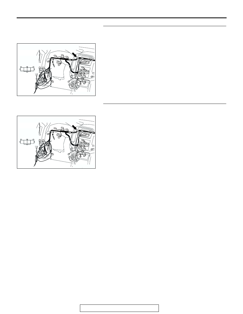
STEP 3. Check hazard warning light switch connector D-
103 for loose, corroded or damaged terminals, or terminals 
pushed back in the connector.
Q: Is hazard warning light switch connector D-103 in good 

condition?
YES : 
Go to Step 4.
NO :  Repair or replace the damaged component(s). Refer 

to GROUP 00E, Harness Connector Inspection 

P.00E-2

. If the equipment, which are described in 

"CIRCUIT OPERATION", work normally, the input 
signal from the hazard warning light switch should be 
normal.

STEP 4. Check the wiring harness between hazard warning 
light switch connector D-103 (terminal 2) and ground.
Q: Is the wiring harness between hazard warning light 

switch connector D-103 (terminal 2) and ground in good 
condition?
YES : 
No action is necessary and testing is complete.
NO :  The wiring harness may be damaged or the 

connector(s) may have loose, corroded or damaged 
terminals, or terminals pushed back in the connector. 
Repair the wiring harness as necessary. If the 
equipment, which are described in "CIRCUIT 
OPERATION", work normally, the input signal from 
the hazard warning light switch should be normal.

AC204170

CONNECTOR : D-103

AK

1

2

4 3

HARNESS 
SIDE

D-103

AC204170

CONNECTOR : D-103

AK

1

2

4 3

HARNESS 
SIDE

D-103

INPUT SIGNAL PROCEDURES

TSB Revision

SWS INPUT SIGNAL PROCEDURES

54Bc-56

STEP 5. Check hazard warning light switch connector D-
103 and ETACS-ECU connector D-224 for loose, corroded 
or damaged terminals, or terminals pushed back in the 
connector.
Q: Are hazard warning light switch connector D-103 and 

ETACS-ECU connector D-224 in good condition?
YES : 
Go to Step 6.
NO :  Repair or replace the damaged component(s). Refer 

to GROUP 00E, Harness Connector Inspection 

P.00E-2

. If the equipment, which are described in 

"CIRCUIT OPERATION", work normally, the input 
signal from the hazard warning light switch should be 
normal.

STEP 6. Check the wiring harness between hazard warning 
light switch connector D-103 (terminal 1) and ETACS-ECU 
connector D-224 (terminal 27).
Q: Is the wiring harness between hazard warning light 

switch connector D-103 (terminal 1) and ETACS-ECU 
connector D-224 (terminal 27) in good condition?
YES : 
Replace the ETACS-ECU. If the equipment, which 

are described in "CIRCUIT OPERATION", work 
normally, the input signal from the hazard warning 
light switch should be normal.

NO :  The wiring harness may be damaged or the 

connector(s) may have loose, corroded or damaged 
terminals, or terminals pushed back in the connector. 
Repair the wiring harness as necessary. If the 
equipment, which are described in "CIRCUIT 
OPERATION", work normally, the input signal from 
the hazard warning light switch should be normal.

AC204170

CONNECTOR : D-103

AK

1

2

4 3

HARNESS 
SIDE

D-103

AC204174

CONNECTOR : D-224

AD

D-224(B)

D-224(B)

HARNESS SIDE

21

23

24

22

32

3433

31

26

27

28

3029

38

39

40

36

37

25

35

AC204170

CONNECTOR : D-103

AK

1

2

4 3

HARNESS 
SIDE

D-103

AC204174

CONNECTOR : D-224

AD

D-224(B)

D-224(B)

HARNESS SIDE

21

23

24

22

32

3433

31

26

27

28

3029

38

39

40

36

37

25

35

INPUT SIGNAL PROCEDURES

TSB Revision

SWS INPUT SIGNAL PROCEDURES

54Bc-57

INSPECTION PROCEDURE P-3: ETACS-ECU does not receive any signal from the driver's seat belt 
switch. 

.

CIRCUIT OPERATION
The ETACS-ECU operates the following functions 
and equipment according to signal from the driver's 
seat belt switch:

• Seat belt tone alarm function

• Seat belt warning light

.

Seat Belt Switch Input Circuit

AC204170

CONNECTOR : D-125

BE

AC204174

CONNECTOR : D-224

D-224(B)

AG

AC204177

CONNECTOR : F-18

AL

INPUT SIGNAL PROCEDURES

TSB Revision

SWS INPUT SIGNAL PROCEDURES

54Bc-58

TECHNICAL DESCRIPTION (COMMENT)
If the signal is not normal, the equipment and func-
tions, which are described in "CIRCUIT OPERA-
TION", do not work normally.

.

TROUBLESHOOTING HINTS

• The driver's inner seat belt (driver's seat belt 

switch) may be defective

• The ETACS-ECU may be defective

• The wiring harness or connectors may have 

loose, corroded, or damaged terminals, or termi-
nals pushed back in the connector

DIAGNOSIS

Required Special Tools:

• MB991223: Harness Set

• MB991502: Scan Tool (MUT-II)

STEP 1. Check the driver's seat belt switch.
Disconnect driver's seat belt switch connector F-18. Then 
check continuity between the switch terminals.

Q: Is the driver's seat belt switch in good condition?

YES : Go to Step 2.
NO :  Replace the driver's inner seat belt. If the functions, 

which are described in "CIRCUIT OPERATION", work 
normally, the input signal from the driver's seat belt 
switch should be normal.

ITEM

TESTER 
CONNECTION

SPECIFIED 
CONDITION

Fastened seat 
belt

− 2

Open circuit

Unfastened seat 
belt

− 2

Less than 2 ohms

ACX00636

TONGUE

BUCKLE

AC


Content   ..  375  376  377  378   ..