Mitsubishi Montero (2002-2004). Manual - part 375


  Index      Mitsubishi     Mitsubishi Montero - service repair manual 2002-2004 year


Search            


Content   ..  373  374  375  376   ..


Mitsubishi Montero (2002-2004). Manual - part 375


INPUT SIGNAL PROCEDURES

TSB Revision

SWS INPUT SIGNAL PROCEDURES

54Bc-47

DIAGNOSIS

Required Special Tools:

• MB991223: Harness Set

• MB991502: Scan Tool (MUT-II)

• MB991862: SWS monitor kit

STEP 1. Check the RV meter.
Q: Does the RV meter work normally?

YES : Go to Step 2.
NO :  First, repair the RV meter. Refer to GROUP 54A, RV 

meter 

P.54A-235

.

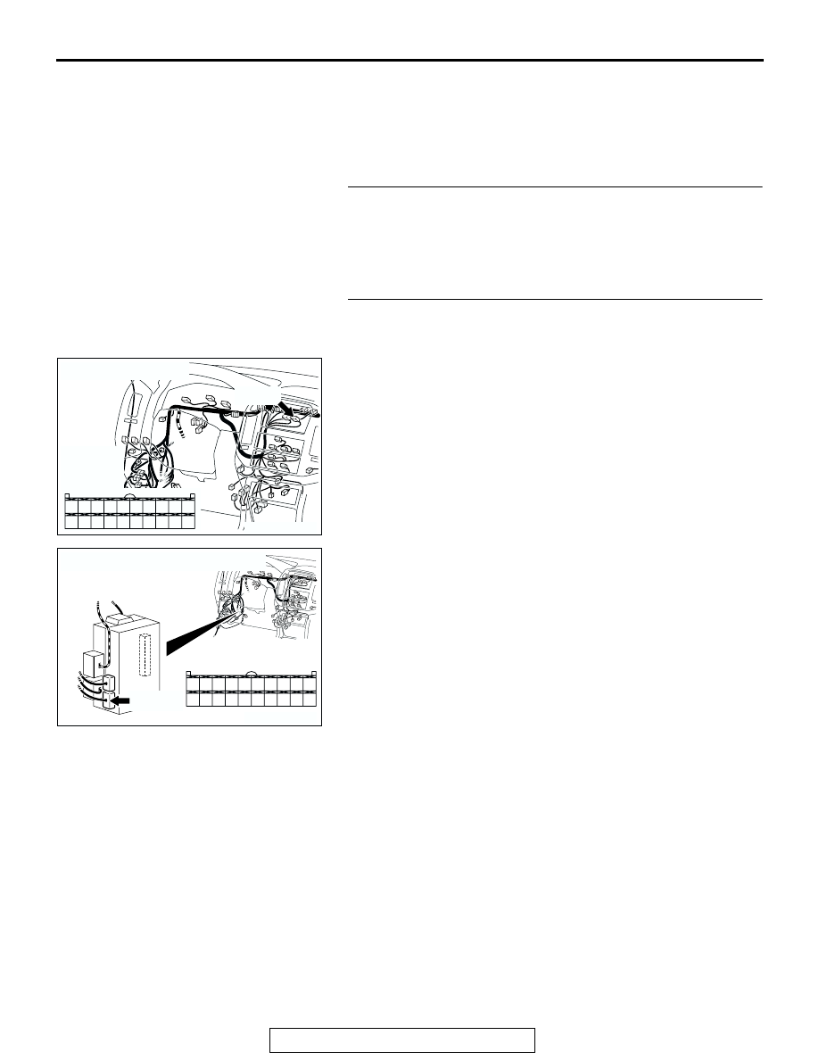
STEP 2. Check RV meter connector D-08 and ETACS-ECU 
connector D-224 for loose, corroded or damaged 
terminals, or terminals pushed back in the connector.
Q: Are RV meter connector D-08 and ETACS-ECU 

connector D-224 in good condition?
YES : 
Go to Step 3.
NO :  Repair or replace the damaged component(s). Refer 

to GROUP 00E, Harness Connector Inspection 

P.00E-2

. If the RV meter operating sound function 

works normally, it indicates that a correct signal is 
sent from the RV meter switch.

AC204170

CONNECTOR : D-08

AE

D-08(B)

HARNESS 
SIDE

D-08(B)

1

3

4

2

12

1413

11

6

7

8

10 9

18

19

20

16

17

5

15

AC204174

CONNECTOR : D-224

AD

D-224(B)

D-224(B)

HARNESS SIDE

21

23

24

22

32

3433

31

26

27

28

3029

38

39

40

36

37

25

35

INPUT SIGNAL PROCEDURES

TSB Revision

SWS INPUT SIGNAL PROCEDURES

54Bc-48

STEP 3. Check the wiring harness between RV meter 
connector D-08 (terminal 6) and ETACS-ECU connector D-
224 (terminal 21).
NOTE: Also check joint connector D-02 for loose, corroded, or 
damaged terminals, or terminals pushed back in the connector. 
If joint connector D-02 is damaged, Repair or replace the dam-
aged component(s) as described in GROUP 00E, Harness 
Connector Inspection 

P.00E-2

Q: Is the wiring harness between RV meter connector D-08 

(terminal 6) and ETACS-ECU connector D-224 (terminal 
21) in good condition?
YES : 
Go to Step 4.
NO :  The wiring harness may be damaged or the 

connector(s) may have loose, corroded or damaged 
terminals, or terminals pushed back in the connector. 
Repair the wiring harness as necessary. If the RV 
meter works normally, it indicates that a correct signal 
is sent from the RV meter switch.

STEP 4. Replace the ECU.
(1) Replace the RV meter.
(2) If the RV meter works normally, it indicates that a correct 

signal is sent from the RV meter switch.

Q: Does the ETACS-ECU receive correct signals from the 

RV meter switch?
YES : 
No action is necessary and testing is complete.
NO :  Replace the ETACS-ECU. If the RV meter works 

normally, it indicates that a correct signal is sent from 
the RV meter switch.

AC204188

CONNECTORS : D-02, D-08

D-08(B)

D-02

AC

D-02

D-08(B)

HARNESS SIDE

9 10

8

6 7

31 32

30

29

18 19 20 21

5

4

2

1

3

27

26

24

23

25

12 13 14 15 16 17

28

11
22
33

1

3

4

2

12

1413

11

6

7

8

10 9

18

19

20

16

17

5

15

AC204174

CONNECTOR : D-224

AD

D-224(B)

D-224(B)

HARNESS SIDE

21

23

24

22

32

3433

31

26

27

28

3029

38

39

40

36

37

25

35

INPUT SIGNAL PROCEDURES

TSB Revision

SWS INPUT SIGNAL PROCEDURES

54Bc-49

INSPECTION PROCEDURE P-1: ETACS-ECU does not receive any signal from the key reminder 
switch.

.

CIRCUIT OPERATION
The ETACS-ECU operates the following functions or 
systems according to signal from the key reminder 
switch:

• Ignition key reminder tone alarm function

• Keyless entry system

• Dome light dimming function

.

Key Reminder Switch Input Circuit

AC204170

CONNECTOR : D-30

BC

AC204172

CONNECTOR : D-202

AF

AC204174

CONNECTOR : D-224

D-224(B)

AG

INPUT SIGNAL PROCEDURES

TSB Revision

SWS INPUT SIGNAL PROCEDURES

54Bc-50

TECHNICAL DESCRIPTION (COMMENT)
If the signal is not normal, the functions or systems, 
which are described in "CIRCUIT OPERATION", do 
not work normally.

.

TROUBLESHOOTING HINTS

• The key reminder switch may be defective

• The ETACS-ECU may be defective

• The wiring harness or connectors may have 

loose, corroded, or damaged terminals, or termi-
nals pushed back in the connector

DIAGNOSIS

Required Special Tools:

• MB991223: Harness Set

• MB991502: Scan Tool (MUT-II)

STEP 1. Check the key reminder switch.
Disconnect key reminder switch connector D-202. Then check 
continuity between terminals.

Q: Is the key reminder switch in good condition?

YES : Go to Step 2.
NO :  Replace the key reminder switch. If the functions, 

which are described in "CIRCUIT OPERATION", work 
normally, the input signal from the key reminder 
switch should be normal.

STEP 2. Check the ground circuit to the key reminder 
switch. Test at key reminder switch connector D-202.
(1) Disconnect key reminder switch connector D-202 and 

measure the resistance available at the wiring harness side 
of the connector.

(2) Measure the resistance value between terminal 4 and 

ground.

• The resistance should equal 2 ohms or less.

Q: Is the measured resistance 2 ohms or less?

YES : Go to Step 5.
NO :  Go to Step 3.

IGNITION KEY

TESTER 
CONNECTION

SPECIFIED 
CONDITION

Inserted

− 6

Open circuit

Removed

− 6

Less than 2 ohms

AC204172

CONNECTOR : D-202

AB

HARNESS SIDE

4

5

3

1

6

7

2

D-203

AC204172

CONNECTOR : D-202

AB

HARNESS SIDE

4

5

3

1

6

7

2

D-203

5 4 3

2

1

7 6

ACX01595AB

CONNECTOR D-202
(HARNESS SIDE)


Content   ..  373  374  375  376   ..