Mitsubishi Montero (2002-2004). Manual - part 360
SYMPTOM PROCEDURES
TSB Revision
SWS SYMPTOM PROCEDURES
54Bb-487
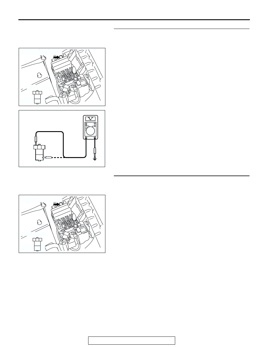
STEP 4. Check the fusible link (2) line of the power supply
circuit to the theft-alarm horn relay. Test at theft-alarm horn
relay connector A-11X.
(1) Disconnect theft-alarm horn relay connector A-11X and
measure the voltage available at the relay box side of the
connector.
(2) Measure the voltage between terminal 3 and ground, and
also between terminal 5 and ground.
• The voltage should be approximately 12 volts (battery
positive voltage).
Q: Is the measured voltage approximately 12 volts (battery
positive voltage)?
YES : Go to Step 7.
NO : Go to Step 5.
STEP 5. Check theft-alarm horn relay connector A-11X for
loose, corroded or damaged terminals, or terminals
pushed back in the connector.
Q: Is theft-alarm horn relay connector A-11X in good
condition?
YES : Go to Step 6.
NO : Repair or replace the damaged component(s). Refer
to GROUP 00E, Harness Connector Inspection
. All the vehicle horn (including the theft-alarm
horn) should sound when the theft-alarm system is
triggered.
AC204183
CONNECTOR : A-11X
RELAY BOX SIDE
AE
2 1
5
4
3
A-11X
1
2
3
4
5
ACX01571AC
CONNECTOR A-11X
(RELAY BOX SIDE)
AC204183
CONNECTOR : A-11X
RELAY BOX SIDE
AE
2 1
5
4
3
A-11X