Mitsubishi Montero (2002-2004). Manual - part 349


  Index      Mitsubishi     Mitsubishi Montero - service repair manual 2002-2004 year


Search            


Content   ..  347  348  349  350   ..


Mitsubishi Montero (2002-2004). Manual - part 349


SYMPTOM PROCEDURES

TSB Revision

SWS SYMPTOM PROCEDURES

54Bb-443

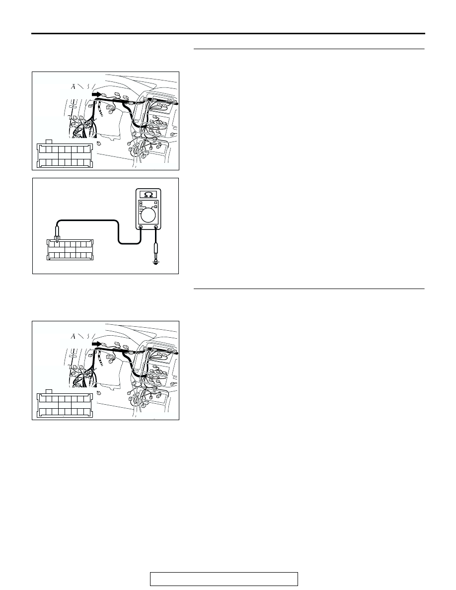
STEP 15. Check the ground circuit to the fog light indicator 
light. Test at combination meter connector D-03.
(1) Disconnect fog light indicator light connector D-03 and 

measure the resistance available at the wiring harness side 
of the connector.

(2) Measure the resistance value between terminal 57 and 

ground.

• The resistance should equal 2 ohms or less.

Q: Is the measured resistance 2 ohms or less?

YES : Go to Step 18.
NO :  Go to Step 16.

STEP 16. Check combination meter connector D-03 for 
loose, corroded or damaged terminals, or terminals 
pushed back in the connector.
Q: Is combination meter connector D-03 in good 

condition?
YES : 
Go to Step 17.
NO :  Repair or replace the damaged component(s). Refer 

to GROUP 00E, Harness Connector Inspection 

P.00E-2

. Verify that the fog light indicator light 

illuminates normally.

AC204170

CONNECTOR : D-03

AC

D-03(GR)

HARNESS 
SIDE

51

52

61 60

53

54

56

57

55

63

66 65 64

59

62

58

67

D-03(GR)

61

62

63

64

65

66

57

58

59

60

51

52

53

54

55

56

67

AC100271AB

CONNECTOR D-03
(HARNESS SIDE)

AC204170

CONNECTOR : D-03

AC

D-03(GR)

HARNESS 
SIDE

51

52

61 60

53

54

56

57

55

63

66 65 64

59

62

58

67

D-03(GR)

SYMPTOM PROCEDURES

TSB Revision

SWS SYMPTOM PROCEDURES

54Bb-444

STEP 17. Check the wiring harness between combination 
meter connector D-03 (terminal 57) and ground.
NOTE: Also check joint connector D-30 for loose, corroded, or 
damaged terminals, or terminals pushed back in the connector. 
If joint connector D-30 is damaged, repair or replace the dam-
aged component(s) as described in GROUP 00E, Harness 
Connector Inspection 

P.00E-2

.

Q: Is the wiring harness between combination meter 

connector D-03 (terminal 57) and ground in good 
condition?
YES : 
No action is necessary and testing is complete.
NO :  The wiring harness may be damaged or the 

connector(s) may have loose, corroded or damaged 
terminals, or terminals pushed back in the connector. 
Repair the wiring harness as necessary. Verify that 
the fog light indicator light illuminates normally.

STEP 18. Check combination meter connector D-04 for 
loose, corroded or damaged terminals, or terminals 
pushed back in the connector. 
Q: Is combination meter connector D-04 in good 

condition?
YES : 
Go to Step 19.
NO :  Repair or replace the damaged component(s). Refer 

to GROUP 00E, Harness Connector Inspection 

P.00E-2

. Verify that the fog light indicator light 

illuminates normally.

AC204188

CONNECTORS : D-03, D-30

D-30

AI

HARNESS SIDE

D-03(GR)

D-30

D-03(GR)

9 10

8

6 7

31 32

30

29

18 19 20 21

5

4

2

1

3

27

26

24

23

25

12 13 14 15 16 17

28

11
22
33

51

52

61 60

53

54

56

57

55

63

66 65 64

59

62

58

67

AC204183

CONNECTOR : A-13X

RELAY BOX SIDE

AF

2 1

5

4

3

A-13X

AC204170

CONNECTOR : D-04

AD

D-04(GR)

HARNESS 
SIDE

D-04(GR)

31

32

41 40

33

34

36

37

35

43

46 45 44

39

42

38

47

SYMPTOM PROCEDURES

TSB Revision

SWS SYMPTOM PROCEDURES

54Bb-445

STEP 19. Check the wiring harness between relay box 
(fuse No.20) and combination meter connector D-04 
(terminal 42).
NOTE: Also check intermediate connector D-28 for loose, cor-
roded, or damaged terminals, or terminals pushed back in the 
connector. If intermediate connector D-28 is damaged, repair or 
replace the damaged component(s) as described in GROUP 
00E, Harness Connector Inspection 

P.00E-2

.

Q: Is the wiring harness between relay box (fuse No.20) 

and combination meter connector D-04 (terminal 42) in 
good condition?
YES : 
Replace the combination meter (printed-circuit 

board). Verify that the fog light indicator light 
illuminates normally.

NO :  The wiring harness may be damaged or the 

connector(s) may have loose, corroded or damaged 
terminals, or terminals pushed back in the connector. 
Repair the wiring harness as necessary. Verify that 
the fog light indicator light illuminates normally.

STEP 20.Check the ground circuit to the fog light (LH). Test 
at fog light (LH) connector A-21.
(1) Disconnect fog light (LH) connector A-21 and measure the 

resistance available at the wiring harness side of the 
connector.

(2) Measure the resistance value between terminal 2 and 

ground.

• The resistance should equal 2 ohms or less.

Q: Is the measured resistance 2 ohms or less?

YES : Go to Step 22.
NO :  Go to Step 21.

AC204188

CONNECTORS : D-04, D-28

D-04(GR)

AK

HARNESS SIDE

D-04(GR)

D-28

D-28

31

32

41 40

33

34

36

37

35

43

46 45 44

39

42

38

47

2 3

27

32

28

33

16

15

4 5

19

18

29

17

34

7 8

35

22

21

9 10

30

36

31

37

25

24

23

6

20

1

14

26

11

13

12

38

AC204167

CONNECTOR : A-21

HARNESS 
SIDE

A-21(B)

A-21(B)

AJ

1

2

AC100270

1

2

AB

CONNECTOR A-21
(HARNESS SIDE)

SYMPTOM PROCEDURES

TSB Revision

SWS SYMPTOM PROCEDURES

54Bb-446

STEP 21. Check the wiring harness between fog light (LH) 
connector A-21 (terminal 2) and ground.
NOTE: Also check intermediate connector A-25 for loose, cor-
roded, or damaged terminals, or terminals pushed back in the 
connector. If intermediate connector A-25 is damaged, repair or 
replace the damaged component(s) as described in GROUP 
00E, Harness Connector Inspection 

P.00E-2

.

Q: Is the wiring harness between fog light (LH) connector 

A-21 (terminal 2) and ground in good condition?
YES : 
No action is necessary and testing is complete.
NO :  The wiring harness may be damaged or the 

connector(s) may have loose, corroded or damaged 
terminals, or terminals pushed back in the connector. 
Repair the wiring harness as necessary. Verify that 
the fog lights illuminate normally.

STEP 22. Check joint connector (2) A-15 for loose, 
corroded or damaged terminals, or terminals pushed back 
in the connector. 
Q: Is joint connector (2) A-15 in good condition?

YES : Go to Step 23.
NO :  Repair or replace the damaged component(s). Refer 

to GROUP 00E, Harness Connector Inspection 

P.00E-2

. Verify that the fog lights illuminate normally.

STEP 23. Check the wiring harness between joint 
connector (2) A-15 (terminal 1) and relay box (fuse No. 20).
Q: Is the wiring harness between joint connector (2) A-15 

(terminal 1) and relay box (fuse No. 20) in good 
condition?
YES : 
No action is necessary and testing is complete.
NO :  The wiring harness may be damaged or the 

connector(s) may have loose, corroded or damaged 
terminals, or terminals pushed back in the connector. 
Repair the wiring harness as necessary. Verify that 
the fog lights illuminate normally.

AC204185

CONNECTORS : A-21, A-25

A-21(B)

A-25(B)

AF

A-25(B)

HARNESS SIDE

A-21(B)

1

2

4

2

3

1

AC204167

CONNECTOR : A-15

AD

14

13

4

1112

5

3

10

8 9

2

7

1

6

AC204167

CONNECTOR : A-15

AD

14

13

4

1112

5

3

10

8 9

2

7

1

6


Content   ..  347  348  349  350   ..