Mitsubishi Montero (2002-2004). Manual - part 348


  Index      Mitsubishi     Mitsubishi Montero - service repair manual 2002-2004 year


Search            


Content   ..  346  347  348  349   ..


Mitsubishi Montero (2002-2004). Manual - part 348


SYMPTOM PROCEDURES

TSB Revision

SWS SYMPTOM PROCEDURES

54Bb-439

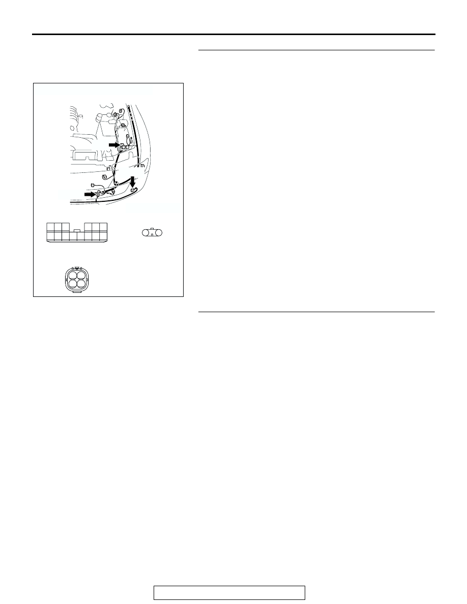
STEP 7. Check the wiring harness between joint connector 
(2) A-15 (terminal 3) and fog light (LH) connector A-21 
(terminal 1).
NOTE: Also check intermediate connector A-25 for loose, cor-
roded, or damaged terminals, or terminals pushed back in the 
connector. If intermediate connector A-25 is damaged, repair or 
replace the damaged component(s) as described in GROUP 
00E, Harness Connector Inspection 

P.00E-2

.

Q: Is the wiring harness between joint connector (2) A-15 

(terminal 3) and fog light (LH) connector A-21 (terminal 
1) in good condition?
YES : 
No action is necessary and testing is complete.
NO :  The wiring harness may be damaged or the 

connector(s) may have loose, corroded or damaged 
terminals, or terminals pushed back in the connector. 
Repair the wiring harness as necessary. Verify that 
the fog lights illuminate normally.

STEP 8. Check the fog light bulb (RH).
(1) Remove the fog light bulb (RH).
(2) Verify that the fog light bulb (RH) is not damaged or burned 

out.

Q: Is the fog light bulb (RH) in good condition?

YES : Go to Step 9.
NO :  Replace the fog light bulb (RH). Verify that the fog 

lights illuminate normally.

AC204185

CONNECTORS : A-15, A-21, A-25

A-21(B)

A-15

AC

A-15

A-25

HARNESS SIDE

A-21(B)

A-25(B)

14

13

4

1112

5

3

10

8 9

2

7

1

6

1

2

4

2

3

1

SYMPTOM PROCEDURES

TSB Revision

SWS SYMPTOM PROCEDURES

54Bb-440

STEP 9. Check the ground circuit to the fog light (RH). Test 
at fog light (RH) connector A-31.
(1) Disconnect fog light (RH) connector A-31 and measure the 

resistance available at the wiring harness side of the 
connector.

(2) Measure the resistance value between terminal 2 and 

ground.

• The resistance should equal 2 ohms or less.

Q: Is the measured resistance 2 ohms or less?

YES : Go to Step 12.
NO :  Go to Step 10.

STEP 10. Check fog light (RH) connector A-31 for loose, 
corroded or damaged terminals, or terminals pushed back 
in the connector.
Q: Is fog light (RH) connector A-31 in good condition?

YES : Go to Step 11.
NO :  Repair or replace the damaged component(s). Refer 

to GROUP 00E, Harness Connector Inspection 

P.00E-2

. Verify that the fog lights illuminate normally.

AC204166

CONNECTOR : A-31

HARNESS 
SIDE

A-31(B)

A-31(B)

AD

1

2

AC100270

1

2

AC

CONNECTOR A-31
(HARNESS SIDE)

AC204166

CONNECTOR : A-31

HARNESS 
SIDE

A-31(B)

A-31(B)

AD

1

2

SYMPTOM PROCEDURES

TSB Revision

SWS SYMPTOM PROCEDURES

54Bb-441

STEP 11. Check the wiring harness between fog light (RH) 
connector A-31 (terminal 2) and ground.
NOTE: Also check intermediate connector A-25 for loose, cor-
roded, or damaged terminals, or terminals pushed back in the 
connector. If intermediate connector A-25 is damaged, repair or 
replace the damaged component(s) as described in GROUP 
00E, Harness Connector Inspection 

P.00E-2

.

Q: Is the wiring harness between fog light (RH) connector 

A-31 (terminal 2) and ground in good condition?
YES : 
No action is necessary and testing is complete.
NO :  The wiring harness may be damaged or the 

connector(s) may have loose, corroded or damaged 
terminals, or terminals pushed back in the connector. 
Repair the wiring harness as necessary. Verify that 
the fog lights illuminate normally.

STEP 12. Check joint connector (2) A-15 and fog light (RH) 
connector A-31 for loose, corroded or damaged terminals, 
or terminals pushed back in the connector. 
Q: Are joint connector (2) A-15 and fog light (RH) 

connector A-31 in good condition?
YES : 
Go to Step 13.
NO :  Repair or replace the damaged component(s). Refer 

to GROUP 00E, Harness Connector Inspection 

P.00E-2

. Verify that the fog lights illuminate normally.

AC204166

CONNECTOR : A-31

HARNESS 
SIDE

A-31(B)

A-31(B)

AD

1

2

AC204167

CONNECTOR : A-25

A-25(B)

A-25(B)

AK

4

2

3

1

AC204167

CONNECTOR : A-15

AD

14

13

4

1112

5

3

10

8 9

2

7

1

6

AC204166

CONNECTOR : A-31

HARNESS 
SIDE

A-31(B)

A-31(B)

AD

1

2

SYMPTOM PROCEDURES

TSB Revision

SWS SYMPTOM PROCEDURES

54Bb-442

STEP 13. Check the wiring harness between joint 
connector (2) A-15 (terminal 2) and fog light (RH) 
connector A-31 (terminal 1).
NOTE: Also check intermediate connector A-25 for loose, cor-
roded, or damaged terminals, or terminals pushed back in the 
connector. If intermediate connector A-25 is damaged, repair or 
replace the damaged component(s) as described in GROUP 
00E, Harness Connector Inspection 

P.00E-2

.

Q: Is the wiring harness between joint connector (2) A-15 

(terminal 2) and fog light (RH) connector A-31 (terminal 
1) in good condition?
YES : 
No action is necessary and testing is complete.
NO :  The wiring harness may be damaged or the 

connector(s) may have loose, corroded or damaged 
terminals, or terminals pushed back in the connector. 
Repair the wiring harness as necessary. Verify that 
the fog lights illuminate normally.

STEP 14. Check the fog light indicator light bulb.
(1) Remove the fog light indicator light bulb.
(2) Verify that the fog light indicator light bulb is not damaged or 

burned out.

Q: Is the fog light indicator light bulb in good condition?

YES : Go to Step 15.
NO :  Replace the fog light indicator light bulb. Verify that 

the fog light indicator light illuminates normally.

AC204185

CONNECTORS : A-15,  A-25

A-15

AL

A-15

A-25

A-25(B)

14

13

4

1112

5

3

10

8 9

2

7

1

6

4

2

3

1

AC204166

CONNECTOR : A-31

HARNESS 
SIDE

A-31(B)

A-31(B)

AD

1

2


Content   ..  346  347  348  349   ..