Mitsubishi Montero (2002-2004). Manual - part 340


  Index      Mitsubishi     Mitsubishi Montero - service repair manual 2002-2004 year


Search            


Content   ..  338  339  340  341   ..


Mitsubishi Montero (2002-2004). Manual - part 340


SYMPTOM PROCEDURES

TSB Revision

SWS SYMPTOM PROCEDURES

54Bb-407

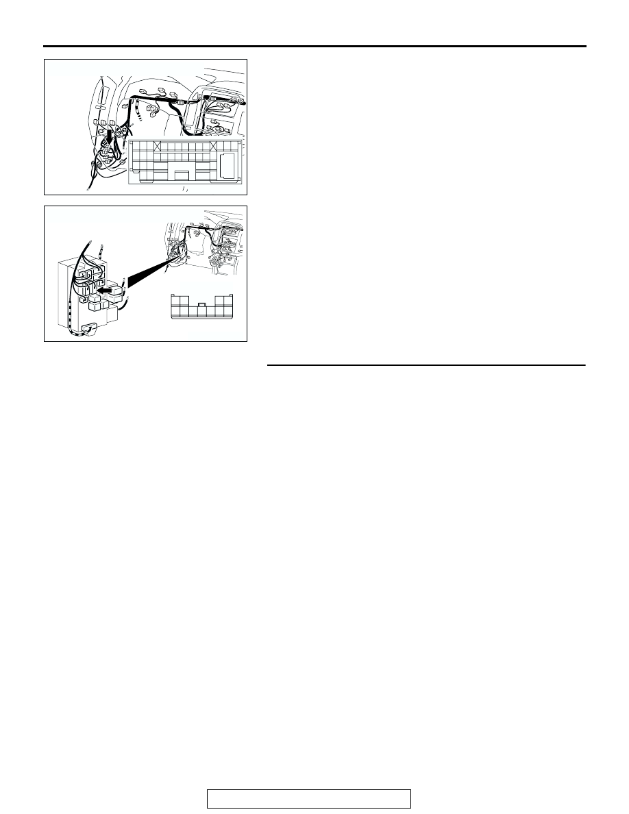
NOTE: Also check junction block connector D-212, joint con-
nector A-16 and intermediate connector D-28 for loose, cor-
roded, or damaged terminals, or terminals pushed back in the 
connector. If junction block connector D-212, joint connector A-
16 or intermediate connector D-28 is damaged, repair or 
replace the damaged component(s) as described in GROUP 
00E, Harness Connector Inspection 

P.00E-2

.

Q: Is the wiring harness between front turn-signal light 

(LH) connector A-19 (terminal 1) and ETACS-ECU 
connector D-222 (terminal 15) in good condition?
YES : 
Replace the socket. Verify that the turn-signal lights 

illuminate normally.

NO :  The wiring harness may be damaged or the 

connector(s) may have loose, corroded or damaged 
terminals, or terminals pushed back in the connector. 
Repair the wiring harness as necessary. Verify that 
the turn-signal lights illuminate normally.

STEP 8. Check the front turn-signal light bulb (RH).
(1) Remove the front turn-signal (RH) light bulb.
(2) Verify that the front turn-signal light bulb (RH) is not 

damaged or burned out.

Q: Is the front turn-signal (RH) light bulb in good 

condition?
YES : 
Go to Step 9.
NO :  Replace the front turn-signal (RH) light bulb. Verify 

that the turn-signal lights illuminate normally.

AC204170

CONNECTOR : D-28

AI

2 3

27

32

28

33

16

15

4 5

19

18

29

17

34

7 8

35

22

21

9 10

30

36

31

37

25

24

23

6

20

1

14

26

11

13

12

38

AC204173

CONNECTOR : D-212

AF

HARNESS SIDE

7 6 5

2 1

9 8

11 10

4 3

D-212

SYMPTOM PROCEDURES

TSB Revision

SWS SYMPTOM PROCEDURES

54Bb-408

STEP 9. Check the ground circuit to the front combination 
light (RH). Test at front combination light (RH) connector 
A-35.
(1) Disconnect front combination light (RH) connector A-35 and 

measure the resistance available at the wiring harness side 
of the connector.

(2) Measure the resistance value between terminal 2 and 

ground.

• The resistance should equal 2 ohms or less.

Q: Is the measured resistance 2 ohms or less?

YES : Go to Step 12.
NO :  Go to Step 10.

STEP 10. Check front turn-signal light (RH) connector A-35 
for loose, corroded or damaged terminals, or terminals 
pushed back in the connector.
Q: Is the front turn-signal (RH) connector A-35 in good 

condition?
YES : 
Go to Step 11.
NO :  Repair or replace the damaged component(s). Refer 

to GROUP 00E, Harness Connector Inspection 

P.00E-2

Verify that the turn-signal lights illuminate 

normally.

AC204166

CONNECTOR : A-35

HARNESS 
SIDE

A-35(B)

A-35(B)

AF

1

2

AC204786

1

2

AC

CONNECTOR A-35
(HARNESS SIDE)

AC204166

CONNECTOR : A-35

HARNESS 
SIDE

A-35(B)

A-35(B)

AF

1

2

SYMPTOM PROCEDURES

TSB Revision

SWS SYMPTOM PROCEDURES

54Bb-409

STEP 11. Check the wiring harness between front turn-
signal light (RH) connector A-35 (terminal 2) and ground.
Q:  Is the wiring harness between front turn-signal light 

(RH) connector A-35 (terminal 2) and ground in good 
condition?
YES : 
Replace the socket. Verify that the turn-signal lights 

illuminate normally.

NO :  The wiring harness may be damaged or the 

connector(s) may have loose, corroded or damaged 
terminals, or terminals pushed back in the connector. 
Repair the wiring harness as necessary. Verify that 
the turn-signal lights illuminate normally.

STEP 12. Check front turn-signal light (RH) connector A-35 
and ETACS-ECU connector D-222 for loose, corroded or 
damaged terminals, or terminals pushed back in the 
connector.
Q: Are front turn-signal light (RH) connector A-35 and 

ETACS-ECU connector D-222 in good condition?
YES : 
Go to Step 13.
NO :  Repair or replace the damaged component(s). Refer 

to GROUP 00E, Harness Connector Inspection 

P.00E-2

Verify that the turn-signal lights illuminate 

normally.

AC204166

CONNECTOR : A-35

HARNESS 
SIDE

A-35(B)

A-35(B)

AF

1

2

AC204166

CONNECTOR : A-35

HARNESS 
SIDE

A-35(B)

A-35(B)

AF

1

2

AC204174

CONNECTOR : D-222

AB

1

2

3

5

6

4

9 8

121110

13

15 14

16

17

7

19

20

18

JUNCTION BLOCK SIDE

D-222

SYMPTOM PROCEDURES

TSB Revision

SWS SYMPTOM PROCEDURES

54Bb-410

STEP 13. Check the wiring harness between front turn-
signal light (RH) connector A-35 (terminal 1) and ETACS-
ECU connector D-222 (terminal 14).

AC204166

CONNECTOR : A-35

HARNESS 
SIDE

A-35(B)

A-35(B)

AF

1

2

AC204174

CONNECTOR : D-222

AB

1

2

3

5

6

4

9 8

121110

13

15 14

16

17

7

19

20

18

JUNCTION BLOCK SIDE

D-222


Content   ..  338  339  340  341   ..