Mitsubishi Montero (2002-2004). Manual - part 332


  Index      Mitsubishi     Mitsubishi Montero - service repair manual 2002-2004 year


Search            


Content   ..  330  331  332  333   ..


Mitsubishi Montero (2002-2004). Manual - part 332


SYMPTOM PROCEDURES

TSB Revision

SWS SYMPTOM PROCEDURES

54Bb-375

DOOR SW": Refer to Inspection Procedure O-5 
"ETACS-ECU does not receive any signal from 
the driver's or the front passenger's door switch 

P.54Bc-23

."

• Normal condition is not displayed on the "H/L 

AUTO-CUT": Replace the front-ECU. Verify that 
the headlight automatic shutdown function now 
works normally.

INSPECTION PROCEDURE J-10: Headlight and Taillight: Headlight dimmer switch automatic resetting 
function does not work normally.

.

CIRCUIT OPERATION
The headlight dimmer switch automatic resetting 
function is controlled by the front-ECU. 

.

TECHNICAL DESCRIPTION (COMMENT)
If the headlight dimmer switch automatic resetting 
function does not work normally, the front-ECU may 
be defective.

.

TROUBLESHOOTING HINT
The front-ECU may be defective 

DIAGNOSIS

Replace the front-ECU.
Verify that the headlight dimmer switch automatic resetting 
function now works normally.

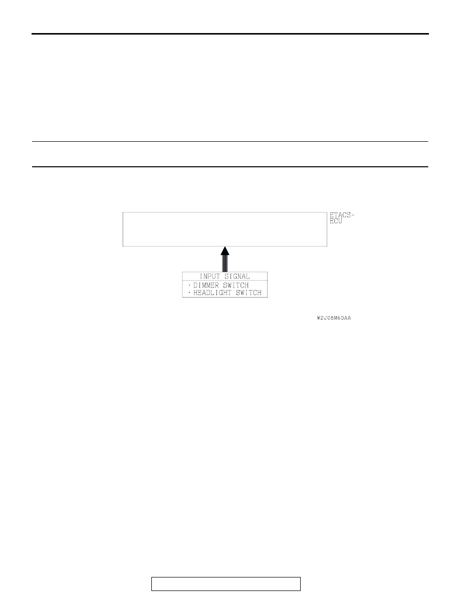
Headlight (Dimmer/Passing) Input Signal

SYMPTOM PROCEDURES

TSB Revision

SWS SYMPTOM PROCEDURES

54Bb-376

INSPECTION PROCEDURE J-11: Headlight and Taillight: Daytime running light function does not 
work normally. <vehicles for Canada>

Daytime Running Light Circuit

AC204167

CONNECTORS : A-15, A-17

A-15

AO

A-17(GR)

AC204166

CONNECTORS : A-32, A-40

AK

A-40(B)

A-32(B)

SYMPTOM PROCEDURES

TSB Revision

SWS SYMPTOM PROCEDURES

54Bb-377

.

TECHNICAL DESCRIPTION (COMMENT) 
If the daytime running light function is not operating 
normally the daytime running light-ECU power circuit 
may be defective or the daytime running light-ECU 
may be defective.

.

TROUBLESHOOTING HINTS

• The daytime running light-ECU may be defective

• The wiring harness or connectors may have 

loose, corroded, or damaged terminals, or termi-
nals pushed back in the connector

DIAGNOSIS

Required Special Tools:

• MB991223: Harness Set

• MB991502: Scan Tool (MUT-II) 

STEP 1. Verify the headlight (low-beam) operation.
Check to see that the headlight (low-beam) lights up properly 
when operating the lighting switch while the headlight switch is 
ON.
Q: Do the headlights (low-beam) illuminate normally?

YES : Go to Step 2.
NO :  Refer to Inspection Procedure J-7 "One of the 

headlights does not illuminate 

P.54Bb-357

."

AC204170

CONNECTOR : D-28

BB

AC204173

CONNECTORS: D-208, D-210

D-208

D-210

AR

SYMPTOM PROCEDURES

TSB Revision

SWS SYMPTOM PROCEDURES

54Bb-378

STEP 2. Check the battery power supply circuit to the 
daytime running light-ECU. Test at daytime running light-
ECU connector A-40.
(1) Disconnect daytime running light-ECU connector A-40 and 

measure the voltage available at the wiring harness side of 
the connector.

(2) Measure the voltage between terminal 1 and ground.

• The voltage should measure approximately 12 volts 

(battery positive voltage).

Q: Is the measured voltage approximately 12 volts (battery 

positive voltage)?
YES : 
Go to Step 5.
NO :  Go to Step 3.

STEP 3. Check daytime running light-ECU connector A-40 
for loose, corroded or damaged terminals, or terminals 
pushed back in the connector.
Q: Is daytime running light-ECU connector A-40 in good 

condition?
YES : 
Go to Step 4.
NO :  Repair or replace the damaged component(s). Refer 

to GROUP 00E, Harness Connector Inspection 

P.00E-2

The daytime running light function should 

now work normally.

AC204166

CONNECTOR : A-40

HARNESS 
SIDE

A-40(B)

A-40(B)

AH

1
4

2

3
6 5

5

6

3 2

4

1

AC204465

CONNECTOR: A-40
(HARNESS SIDE)

AB

AC204166

CONNECTOR : A-40

HARNESS 
SIDE

A-40(B)

A-40(B)

AH

1
4

2

3
6 5


Content   ..  330  331  332  333   ..