Mitsubishi Montero (2002-2004). Manual - part 228


  Index      Mitsubishi     Mitsubishi Montero - service repair manual 2002-2004 year


Search            


Content   ..  226  227  228  229   ..


Mitsubishi Montero (2002-2004). Manual - part 228


PROPELLER SHAFT DIAGNOSIS

TSB Revision

PROPELLER SHAFT

25-3

SYMPTOM CHART

M1251002000044

SYMPTOM PROCEDURES

INSPECTION PROCEDURE 1: Noise at Start

DIAGNOSIS

STEP 1. Check if the propeller shaft mounting 
bolts and nuts are loose. (Refer to 

P.25-5

.)

Q: Are the bolts and nuts tightened to 60 

± 10 Nm (45 

± 7 ft-lb)?

YES : 

Go to Step 2.

NO : 

Tighten the bolts and nuts to 60 

± 10 N⋅m 

(45 

± 7 ft-lb). Then go to Step 5.

STEP 2. Check the universal joint's journal 
bearing of front propeller shaft for wear or 
damage. (Refer to 

P.25-10

.)

Q: Is wear or damage apparent?

YES : 

Replace the journal bearing. Then go to 

Step 5.

NO : 

Go to Step 3.

STEP 3. Check the BJ assembly's spline of front 
propeller shaft for wear.

Q: Is wear apparent?

YES : 

Replace the propeller shaft. Then go to Step 

5.

NO : 

Go to Step 4.

STEP 4. Check the flange sleeve spline of rear 
propeller shaft for wear.

Q: Is wear apparent?

YES : 

Replace the rear propeller shaft. Then go to 

Step 5.

NO : 

Go to Step 5.

STEP 5. Retest the system.

Q: Is the abnormal noise eliminated?

YES : 

The procedure is complete.

NO : 

Recheck from Step 1.

INSPECTION PROCEDURE 2: Noise and Vibration at High Speed

DIAGNOSIS

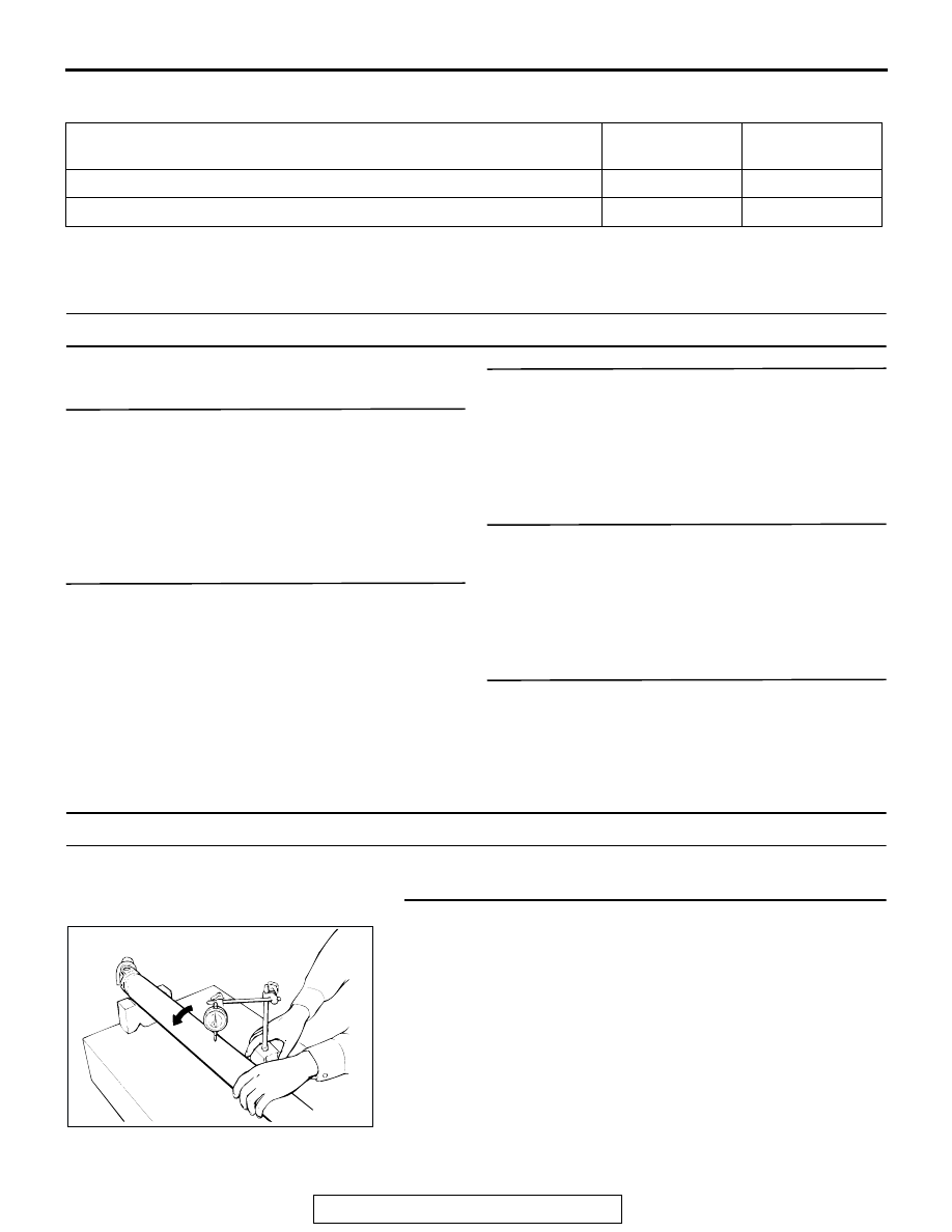
STEP 1. Check the front propeller shaft run-out.
Q: Is the measured value within the limit: 0.5 mm (0.02 

inch)?
YES : 
Go to Step 2. 
NO :  Replace the front propeller shaft. Then go to Step 6.

SYMPTOMS

INSPECTION 
PROCEDURE

REFERENCE 
PAGE

Noise at start

1

P.25-3

Noise and vibration at high speed

2

P.25-3

ACX00643

SPECIAL TOOL

TSB Revision

PROPELLER SHAFT

25-4

STEP 2. Check the front propeller shaft snap rings 
thickness. (Refer to 

P.25-10

.)

Q: Are they correct?

YES : Go to Step 3. 
NO :  Replace the snap ring. Then go to Step 6.

STEP 3. Check the front propeller shaft journal bearings 
for wear or damage. (Refer to 

P.25-10

.)

Q: Is wear or damage apparent?

YES : Replace the journal bearing. Then go to Step 6. 
NO :  Go to Step 4.

STEP 4. Check the rear propeller shaft for wear or damage. 
(Refer to 

P.25-9

.)

Q: Is wear or damage apparent?

YES : Replace the rear propeller shaft. Then go to Step 6. 
NO :  Go to Step 5.

STEP 5. Measure the clearance between the tube and the 
shaft at the end portion of the rear propeller shaft tube.
Q: Is the measured value is within the standard value: 0.2 


0.5 mm (0.008 

 0.020 inch)?

YES : Go to Step 6.
NO :  Replace the rear propeller shaft. Then go to Step 6.

STEP 6. Retest the system.
Q: Is the abnormal noise eliminated?

YES : The procedure is complete.
NO :  Recheck from Step 1.

SPECIAL TOOL

M1251000600062

ACX00920

TOOL

TOOL NUMBER AND 
NAME

SUPERSESSION

APPLICATION

MB990840
Universal joint remover/
installer

MB990840-01

Disassembly and 
reassembly of universal 
joint

MB990840

PROPELLER SHAFT

TSB Revision

PROPELLER SHAFT

25-5

PROPELLER SHAFT

REMOVAL AND INSTALLATION

M1251001000148

WARNING

Since the rear propeller shaft is made of CFRP, it is 
important to observe the following warning items 
strictly.

If a tear, chip or distortion is found on the tube, 
replace it with new one.

Do not drop, shock, or scratch the tube.

If the propeller shaft is scratched on the surface, 
inspect whether it is damaged or not using a dye 
penetrant. (Refer to 

P.25-9

.)

If the propeller shaft is dropped on the ground, 
replace it with new one. If the dropped rear propel-
ler shaft is reinstalled, the rear propeller shaft may 
be broken.

When working with the propeller shaft, wrap the 
propeller shaft tube with the rubber sheet of 10 
mm (0.39 inch) thick and over or with the propeller 
shaft protector (part number MR534564) so that it 
is not scratched.

If a crack or a tear is found on the seal portion at 
the end of CFRP tube shown in the illustration, 
replace the tube with new one.

Dispose of the damaged CFRP propeller shaft in 
compliance with Federal, state, and local laws. For 
disposing of CFRP products, we do not recom-
mend incineration.

ACX00638 AB

RUBBER SHEET OR 
PROPELLER SHAFT PROTECTOR

ACX00639AB

SEAL

SEAL

CFRP TUBE

PROPELLER SHAFT

TSB Revision

PROPELLER SHAFT

25-6

REMOVAL SERVICE POINTS

.

<<A>> FRONT PROPELLER SHAFT ASSEMBLY REMOVAL
1. Move the transfer shift lever to "2H."
2. Drain transfer gear oil. (Refer to GROUP 23, On-vehicle 

Service 

P.23Aa-23

.)

3. Make mating marks on the differential companion flange and 

the flange yoke.

Pre-removal Operation
• Wrap a rubber sheet around the rear CFRP propeller 

shaft. <Before removing the rear CFRP propeller shaft>

Post-installation Operation
• Remove the rubber sheet wrapped around the rear CFRP 

propeller shaft and visually check whether the shaft is 

scratched. <After mounting the rear CFRP propeller 

shaft>

• Transfer Gear Oil Supplying <After mounting the front pro-

peller shaft> (Refer to GROUP 23, On-vehicle Service 

P.23Aa-23

.)

REMOVAL STEPS

<<A>> >>B<<

1.

FRONT PROPELLER SHAFT 
ASSEMBLY

<<B>> >>A<<

2.

REAR PROPELLER SHAFT 
ASSEMBLY

ACX00640 AB

GEAR OIL:
HYPOID GEAR OIL API 
CLASSIFICATION
GL-4 OR HIGHER/SAE VISCOSITY 
80W, 75 - 85W

60 ±


10 N

·

m

45 ±


7 ft-lb

1

60 ±


10 N

·

m

45 ±


7 ft-lb

2


Content   ..  226  227  228  229   ..