Mitsubishi Montero (2002-2004). Manual - part 214


  Index      Mitsubishi     Mitsubishi Montero - service repair manual 2002-2004 year


Search            


Content   ..  212  213  214  215   ..


Mitsubishi Montero (2002-2004). Manual - part 214


DIFFERENTIAL CARRIER AND FREE WHEELING CLUTCH

TSB Revision

FRONT AXLE

26-53

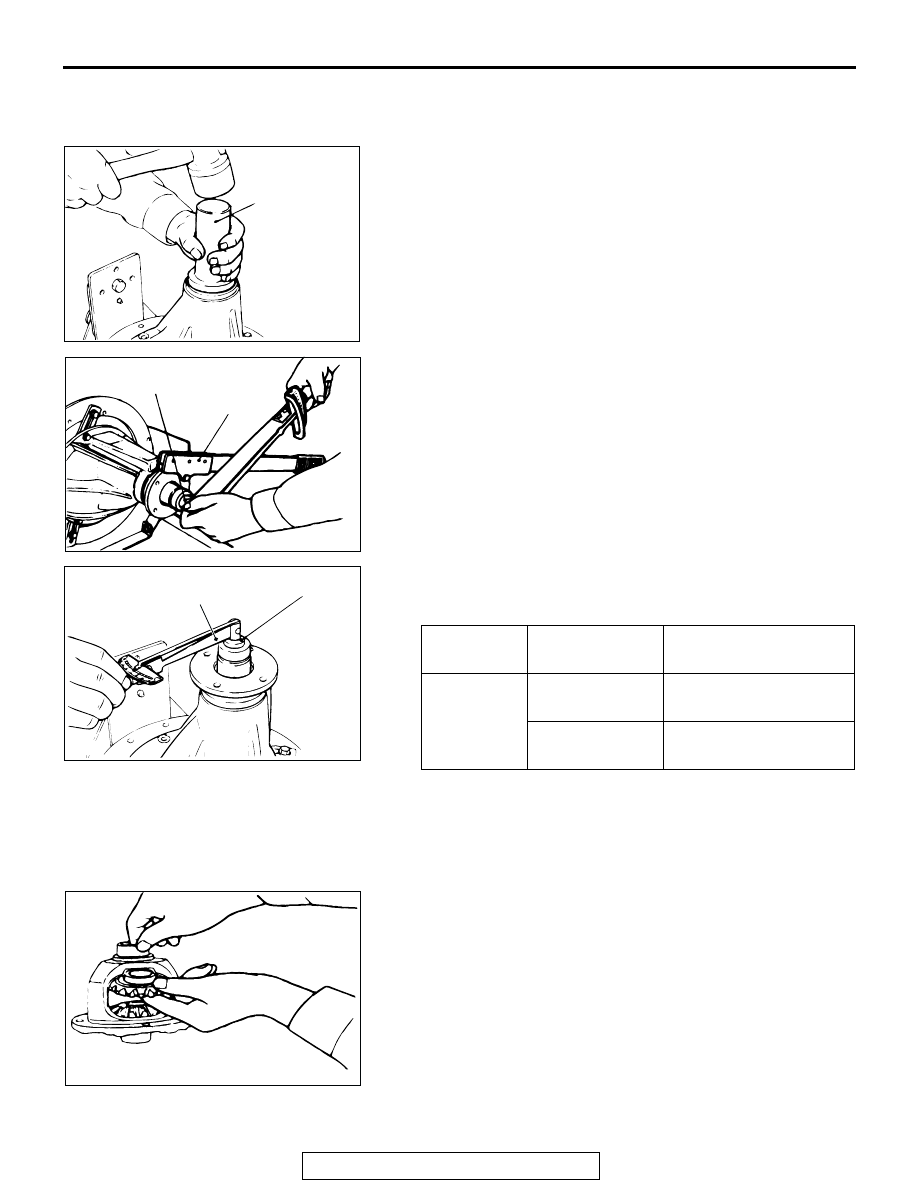
NOTE: Apply gear oil around the circumference of compan-
ion flange (and the mating surface of oil seal) when press fit-
ting oil seal into companion flange.

5. Remove the companion flange and drive pinion again. Then, 

after inserting the drive pinion rear bearing inner race into 
the gear carrier, use special tool MB990031 or MB990699 to 
press-fit the oil seal.

6. Install the drive pinion assembly and companion flange with 

the mating marks properly aligned, and tighten the 
companion flange self-locking nut to the specified torque by 
using special tool MB990850.

7. Measure the drive pinion turning torque (with the oil seal) by 

using special tools.

Standard value: (With oil seal)

8. If the drive pinion turning torque is not within the standard 

value, check the tightening torque of the companion flange 
self-locking nut and the oil seal.

.

>>F<< DIFFERENTIAL GEAR BACKLASH ADJUSTMENT
1. Assemble the side gears, side gear spacers, pinion gears 

and pinion washers into the differential case.

2. Temporarily install the pinion shaft.

NOTE: Do not drive in the lock pin yet.

BEARING 
DIVISION

BEARING 
LUBRICATION

TURNING TORQUE

New

None (with anti-
rust agent)

0.93 

− 1.28 N⋅m (8.24 − 

11.32 in-lb)

Gear oil applied

0.97 

− 1.32 N⋅m (8.59 − 

11.68 in-lb)

ACX01064AB

MB990031
OR
MB990699

ACX01065AB

MB990850

216 

± 

29 N

m

159 

± 

22 ft-lb

ACX01062AB

MB990326

MB990685

ACX01066AB

DIFFERENTIAL CARRIER AND FREE WHEELING CLUTCH

TSB Revision

FRONT AXLE

26-54

3. Insert a wedge between the side gear and the pinion shaft to 

lock the side gear.

4. Measure the differential gear backlash with a dial indicator 

on the pinion gear.

Standard value: 0 

 0.076 mm (0  0.0030 inch)

Limit: 0.2 mm (0.007 inch)

5. If the differential gear backlash exceeds the limit, adjust the 

backlash by installing thicker side gear spacers.

6. If adjustment is not possible, replace the side gears and 

pinion gears as a set.

7. Measure the differential gear backlash once again, and 

confirm that it is within the limit.

.

>>G<< LOCK PIN INSTALLATION
1. Align the pinion shaft lock pin hole with the differential case 

lock pin hole, and drive in the lock pin.

2. Stake the lock pin with a punch at two points.

.

>>H<< DRIVE GEAR INSTALLATION
1. Clean the drive gear attaching bolts.
2. Remove the adhesive adhered to the threaded holes of the 

drive gear by turning the special tool MB990813 (tap M10 x 
1.25), and then clean the threaded holes by applying 
compressed air.

3. Apply the specified adhesive to the threaded holes of the 

drive gear.

Specified adhesive: 3M

ä AAD Part number 8730, 8731 

or equivalent

4. Install the drive gear onto the differential case with the 

mating marks properly aligned. Tighten the bolts to the 
specified torque in a diagonal sequence.

Tightening torque: 83 

± 5 Nm (62 ± 3 ft-lb)

.

AC102885

WEDGE

SIDE GEAR
SPACER

SIDE GEAR
SPACER

AC

ACX01067AB

ACX01068AB

TAP

AC000438 AB

DIFFERENTIAL CARRIER AND FREE WHEELING CLUTCH

TSB Revision

FRONT AXLE

26-55

>>I<< SIDE BEARING INNER RACE INSTALLATION
Use special tool MB990802 to press-fit the side bearing inner 
races into the differential case.

.

>>J<< DRIVE GEAR BACKLASH ADJUSTMENT
Adjust the drive gear backlash by the following procedures:
1. Install the side bearing spacers, which are thinner than 

those removed, to the side bearing outer races, and then 
mount the differential case assembly into the gear carrier.
NOTE: Select side bearing spacers with the same thickness 
for both the drive pinion side and the drive gear side.

2. Push the differential case assembly to one side, and 

measure the clearance between the gear carrier and the 
side bearing adjusting spacer with a feeler gauge.

3. Measure the thickness of the side bearing adjusting spacers 

on one side, select two pairs of spacers which correspond to 
that thickness plus one half of the clearance plus 0.05 mm 
(0.002 inch), and then install one pair each to the drive 
pinion side and the drive gear side.

ACX01069AB

MB990829

PIECE 
OF 
METAL

MB990829

PIECE OF 
METAL

ACX01070AB

ACX01071AB

ACX01072 AB

CLEARANCE / 2 + 0.05 mm
= THICKNESS OF THE 
   SPACER ON ONE SIDE

DIFFERENTIAL CARRIER AND FREE WHEELING CLUTCH

TSB Revision

FRONT AXLE

26-56

4. Install the side bearing adjusting spacers and differential 

case assembly, as shown in the illustration, to the gear 
carrier.

5. Tap the side bearing adjusting spacers with the special tool 

to fit them to the side bearing outer race.

6. Align the mating marks on the gear carrier and the bearing 

cap, and then tighten the bearing cap.

7. With the drive pinion locked in place, measure the drive gear 

backlash with a dial indicator on the drive gear.
NOTE: Measure at four points or more on the circumference 
of the drive gear.

Standard value: 0.11 

 0.16 mm (0.004  0.006 inch)

8. Change the side bearing adjusting spacers as illustrated, 

and then adjust the drive gear backlash between the drive 
gear and the drive pinion.
NOTE: When increasing the number of side bearing adjust-
ing spacers, use the same number for each, and as few as 
possible.

9. Check the drive gear and drive pinion for tooth contact. If 

poor contact is evident, make adjustment. (Refer to 

P.26-

41

.)

ACX01070AB

ACX01073 AB

MB990939

ACX01074AB

ACX01034AB

ACX01075

IF BACKLASH IS TOO SMALL

IF BACKLASH IS TOO LARGE

THINNER
SPACER

THICKER
SPACER

AB

THINNER
SPACER

THICKER
SPACER


Content   ..  212  213  214  215   ..