Mitsubishi Montero (2002-2004). Manual - part 208


  Index      Mitsubishi     Mitsubishi Montero - service repair manual 2002-2004 year


Search            


Content   ..  206  207  208  209   ..


Mitsubishi Montero (2002-2004). Manual - part 208


DRIVE SHAFT ASSEMBLY

TSB Revision

FRONT AXLE

26-29

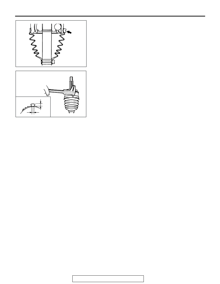
12.Install the UJ boot band (large) to the UJ boot.
13.Use special tool MB991561 to crimp the UJ boot band 

(large) in the same way as in step 6.

14.Check that the crimping amount (B) of the UJ boot band is 

at the standard value and that the crimping amount (C) of 
the UJ boot band is at the limited value.

Standard value (B): 2.4 

 2.8 mm (0.10  0.11 inch)

Limited value (C): 9.5 mm (0.40 inch)

• If the crimping amount is larger than 2.8 mm (0.11 

inch), readjust the value of (W) in step 11 according 
to the following formula, and then repeat the opera-
tion in step 13. 
W = 5.8 mm (0.23 inch) 

 B 

Example: If B = 2.9 mm (0.11 inch), then W = 2.9 mm 
(0.11 inch). 

• If the crimping amount is smaller than 2.4 mm (0.09 

inch), remove the UJ boot band, readjust the value 
of (W) in step 11 according to the following for-
mula, and then repeat the operations in steps 12 
and 13 using a new UJ boot band. 
W = 5.8 mm (0.23 inch) 

 B 

Example: If B = 2.3 mm (0.10 inch) then W = 3.5 mm 
(0.15 inch).

15.Check that the UJ boot band is not sticking out past the 

place where it has been installed. If the UJ boot band is 
sticking out, remove it and then repeat the operations in 
steps 12 to 14 using a new UJ boot band.

AC000425

ACX00997AB

B

C

INNER SHAFT ASSEMBLY

TSB Revision

FRONT AXLE

26-30

INNER SHAFT ASSEMBLY

REMOVAL AND INSTALLATION

M1261004000096

Required Special Tools:

• MB990211: Sliding Hammer

• MB990906: Driveshaft Attachment

Pre-removal and Post-installation Operation
• Removal and Installation of Under Cover.

• Removal and Installation of Skid Plate (Refer to GROUP 

51 - Front Bumper 

P.51-3

.)

• Drive Shaft <RH> Removal and Installation (Refer to 

P.26-23

.)

ACX00998AB

69 

± 

9 N

·

m *

51 

± 

7 ft-lb *

69 

± 

9 N

·

m *

51 

± 

7 ft-lb *

89 

± 

9 N

·

m

65 

± 

7 ft-lb

17 

± 

3 N

·

m

25 

± 

5 N

·

m

22 

± 

4 ft-lb

90 

± 

10 N

·

m

67 

± 

7 ft-lb

12 

± 

2 N

·

m

107 

± 

17 in-lb

12 

± 

2 N

·

m

107 

± 

17 in-lb

1

3

10

5

8

2

4

7

6

9


  REMOVAL 

STEPS

 <<A>> >>B<

1. INNER 

SHAFT


2. CLIP


3.

COLLAR

4. PIN


5. ACTUATOR 

ASSEMBLY


6. VACUUM 

TANK 

ASSEMBLY


7. 

ENGAGE SWITCH ASSEMBLY

 <<B>>   >>A<< 

LOOSENING AND TIGHTENING 
OF DIFFERENTIAL MOUNTING 
INSULATOR BOLT


SUPPORT THE DIFFERENTIAL 
WITH A TRANSMISSION JACK.


8. DIFFERENTIAL 

MOUNTING 

BRACKET <RH>


9. BREATHER 

PIPE


10. HOUSING 

TUBE


REMOVAL STEPS (Continued)

INNER SHAFT ASSEMBLY

TSB Revision

FRONT AXLE

26-31

REMOVAL SERVICE POINTS

.

<<A>> INNER SHAFT REMOVAL

CAUTION

When pulling the inner shaft out from the front differential 
carrier, be careful that the spline part of the inner shaft 
does not damage the oil seal.

.

<<B>> LOOSENING DIFFERENTIAL MOUNTING 
INSULATOR BOLT
Loosen the bolt shown in the diagram.

INSTALLATION SERVICE POINTS

.

<<A>> DIFFERENTIAL MOUNTING INSULATOR BOLT 
TIGHTENING

CAUTION

Place the vehicle on the ground after temporarily tighten-
ing bolts to prevent bushing from twisting, then fully 
tighten the bolts in the unladen condition.
Tighten the bolts shown in the diagram to the specified torque 
in the order of A, B, C, D or A, C, B, D.

Specified torque: 69 

± 9 Nm (51 ± 7 ft-lb)

.

>>B<< INNER SHAFT INSTALLATION

CAUTION

Be careful not to damage the lip of the dust seal and oil 
seal.

ACX00999AB

MB990906

MB990211

ACX01000 AB

ACX01000AC

C

B

D

A

INNER SHAFT ASSEMBLY

TSB Revision

FRONT AXLE

26-32

 DISASSEMBLY AND ASSEMBLY

M1261004200090

Required Special Tools:

• MB990560: Bearing Remover

• MB990938: Bearing and Oil Seal Installer Set

• MB990955: Oil Seal Installer

DISASSEMBLY SERVICE POINT

.

<<A>> BEARING REMOVAL
1. Bend the outside periphery of dust cover inward with a 

wooden hammer.

ACX01001AB

5

3

2

1

5

4

3


DISASSEMBLY 

STEPS


1. INNER 

SHAFT

<<A>> >>C<<

2. BEARING

 >>B<<

3.

DUST COVER


4. HOUSING 

TUBE

 >>A<<

5. DUST 

SEAL

ACX01002AB


Content   ..  206  207  208  209   ..