Mitsubishi Montero (2002-2004). Manual - part 206


  Index      Mitsubishi     Mitsubishi Montero - service repair manual 2002-2004 year


Search            


Content   ..  204  205  206  207   ..


Mitsubishi Montero (2002-2004). Manual - part 206


HUB AND KNUCKLE ASSEMBLY

TSB Revision

FRONT AXLE

26-21

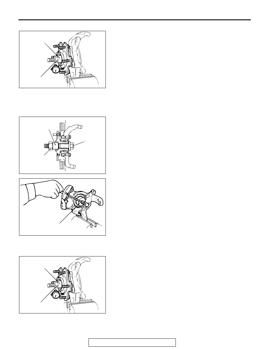
WHEEL BEARING BACKLASH CHECK
1. Secure the knuckle in a vice to measure backlash in the 

wheel bearing.

Limit: 0 mm (0 inch)

2. If the value of backlash in hub axis cannot be obtained when 

tightened to the specified torque 255 

± 29 N⋅m (188 ± 21 ft-

lb), check mounting bolt for hub and knuckle assembly. If no 
defects are found, replace hub assembly.

INSPECTION OF HUB ROTATION STARTING 
TORQUE

M1261007200033

1. Tighten special tools in hub and knuckle assembly to the 

specified torque. 

Specified torque: 255 

± 29 Nm (188 ± 21 ft-lb)

2. Measure the hub rotation starting torque with special tools.

Limit: 1.75 N

m (15.48 in-lb)

3. Hub rotation starting torque must be under the limit value 

and there should be no roughness when rotating the hub. 

WHEEL BEARING PLAY CHECK

M1261001100124

1. Secure the knuckle in a vice to measure backlash in the 

wheel bearing.

Limit: 0 mm (0 inch)

2. If the value of backlash in hub axis cannot be obtained when 

tightened to the specified torque 255 

± 29 N⋅m (188 ± 21 ft-

lb), check mounting bolt for hub and knuckle assembly. If no 
defects are found, replace hub assembly.

ACX00977AB

MB990998

255 

± 

29 N

m

188 

± 

21 ft-lb

ACX00975 AB

MB990998

BOLT

255 

± 

29 N

m

188 

± 

21 ft-lb

HOLD THE BOLT 
AND TIGHTEN THE 
NUT.

ACX00976 AB

MB990326

ACX00977AC

MB990998

255 

± 

29 N

·

m

188 

± 

21 ft-lb

HUB AND KNUCKLE ASSEMBLY

TSB Revision

FRONT AXLE

26-22

 DISASSEMBLY AND ASSEMBLY

M1261006000036

ACX00978 AB

88 

± 

10 N

·

m

65 

± 

7 ft-lb

1

2


DISASSEMBLY 

STEPS 


1. KNUCKLE


2. 

FRONT HUB ASSEMBLY

DRIVE SHAFT ASSEMBLY

TSB Revision

FRONT AXLE

26-23

DRIVE SHAFT ASSEMBLY

REMOVAL AND INSTALLATION

M1261003500292

Required Special Tool:

• MB990767: Front Hub and Flange Yoke Holder

Pre-removal and Post-installation Operation
• Removal and Installation of Under Cover.

• Removal and Installation of Skid Plate (Refer to GROUP 

51- Front Bumper 

P.51-3

.)

• Connection and Disconnection of Shock Absorber and 

Stabilizer Link in the Lower Arm Side (Refer to GROUP 

33- Lower Arm 

P.33A-15

.)

• Removal and Installation of Front Brake Assembly (Refer 

to GROUP 35A 

P.35A-140

.)

• Connection and Disconnection of Knuckle and Tie Rod 

End (Refer to GROUP 37 - Steering Gear Box Assembly 

P.37A-27

.)

ACX00979 AB

60 

± 

10 N

·

m

45 

± 

7  ft-lb

25 

± 

4 N

·

m

18 

±

 3 ft-lb

255 

± 

29 N

·

m

188 

± 

21 ft-lb

<RH> 7

8

<LH> 7

2

3

1

6

5

4


REMOVAL 

STEPS


1. HUB 

CAP

<<A>> >>B<< 

2. CASTLE 

NUT

 >>B<<

3. WASHER


4. BRAKE HOSE AND VEHICLE SPEED 

SENSOR CLAMP BRACKET


5.  WHEEL SPEED SENSOR


6.  UPPER ARM AND UPPER ARM 

BALL JOINT CONNECTION

<<B>> >>A<<

7. DRIVE 

SHAFT


8. CIRCLIP 

<LH>


REMOVAL 

STEPS 

(Continued)

DRIVE SHAFT ASSEMBLY

TSB Revision

FRONT AXLE

26-24

REMOVAL SERVICE POINTS

.

<<A>> CASTLE NUT REMOVAL

CAUTION

Do not apply pressure to the wheel bearing by the vehicle 
weight to avoid possible damage when castle nut is loos-
ened. 

.

<<B>> DRIVE SHAFT REMOVAL

CAUTION

When pulling the drive shaft out from the differential car-
rier, be careful that the spline part of the drive shaft does 
not damage the oil seal. 

INSTALLATION SERVICE POINTS

.

>>A<< DRIVE SHAFT INSTALLATION

CAUTION

Do not damage the oil seal of the differential carrier by the 
drive shaft splines. 

.

>>B<< WASHER/CASTLE NUT INSTALLATION
1. Install washer with castle nut with its smaller side facing the 

castle nut.

2. Tighten castle nut fully, using special tool MB990767.

CAUTION

Do not apply pressure to wheel bearing by the vehicle 
weight to avoid possible damage when castle nut is loos-
ened. 
3. In this case, if the pin holes do not match, tighten the pin to 

255 

± 29 N⋅m (188 ± 21 ft-lb) and find the most suitable hole 

to bend the nut with a split pin.

ACX00972 AB

MB990767

ACX00973AB

WASHER

ACX00974 AB

MB990767

255 

± 

29 N

m

188 

± 

21 ft-lb


Content   ..  204  205  206  207   ..