Mitsubishi Montero (2002-2004). Manual - part 1147
M-ASTC CONTROL UNIT(M-ASTC-ECU)
TSB Revision
MITSUBISHI ACTIVE SKID AND TRACTION CONTROL SYSTEM
35C-205
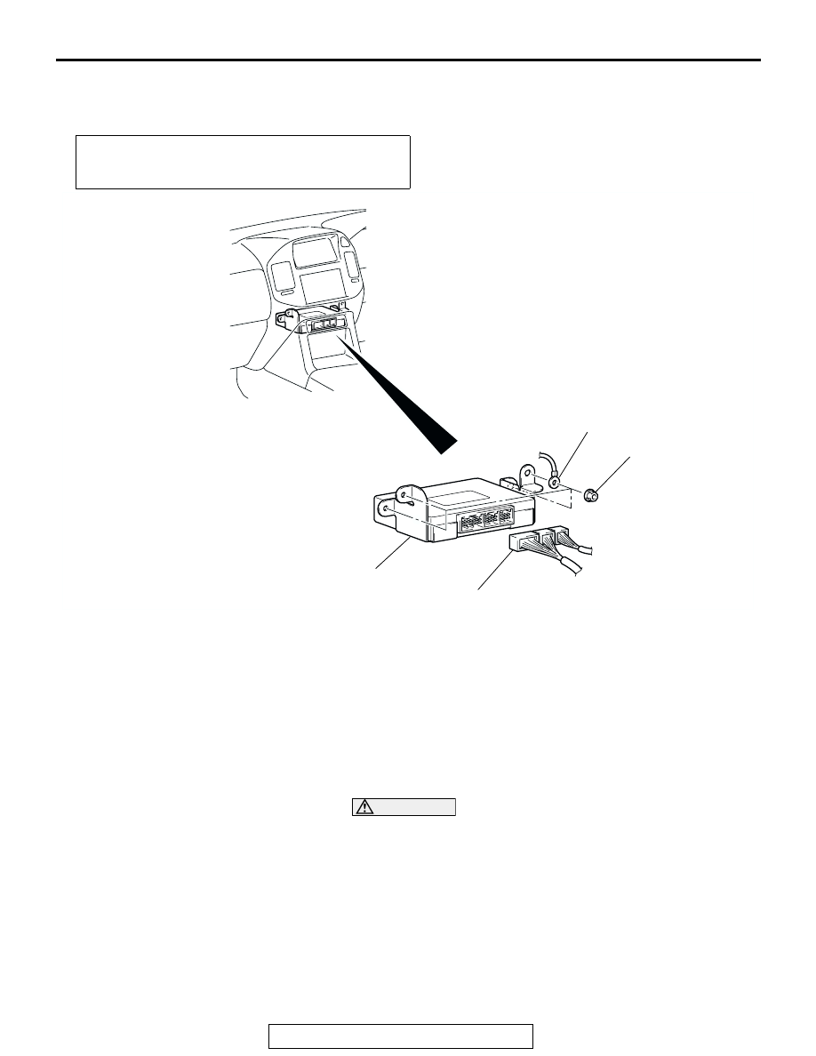
M-ASTC CONTROL UNIT(M-ASTC-ECU)
REMOVAL AND INSTALLATION
M1353002500020
INSTALLATION SERVICE POINTS
.
>>A<< M-ASTC-ECU INSTALLATION
CAUTION
Perform the following initialization procedure, otherwise
the following DTCs will be set.
• DTC No.81: G NO ADJ
• DTC No.84: TF NO CHECK
• DTC No.85: M/CYL PRS NO CHECK
When installing a new M-ASTC-ECU, perform the initialization
as follows, ensuring that the vehicle remains level.
1. Place the selector lever in the "P" position.
Pre-removal and Post-installation Operation
• Indicator Panel, Lower Center Panel Removal and instal-
lation (Refer to GROUP 52A, Floor Console
AC204232
5.0 ± 1.0 N·m
44 ± 9 in-lb
1
3
AB
2
REMOVAL STEPS
>>B<<
• CANCELLING THE HBB BUZZER
OPERATION CHECK MODE (WHEN
REPLACING THE ABS-ECU)
1. M-ASTC-ECU CONNECTOR
2. GROUND
>>A<<
3. M-ASTC-ECU
REMOVAL STEPS (Continued)