Mitsubishi Montero (2002-2004). Manual - part 1140


  Index      Mitsubishi     Mitsubishi Montero - service repair manual 2002-2004 year


Search            


Content   ..  1138  1139  1140  1141   ..


Mitsubishi Montero (2002-2004). Manual - part 1140


M-ASTC DIAGNOSIS

TSB Revision

MITSUBISHI ACTIVE SKID AND TRACTION CONTROL SYSTEM

35C-177

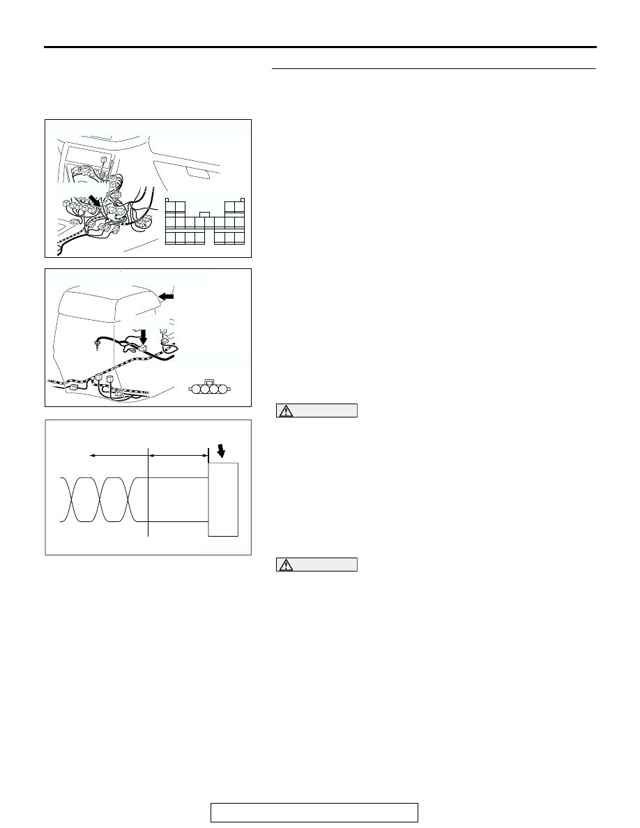
STEP 1. Check G and yaw rate sensor connector E-126 and 
intermediate connector E-123.

CAUTION

If there is a problem in the connector(s) (including terminals) or 
wire(s) of the instrument panel wiring harness assembly (the wir-
ing harness connected to the steering wheel sensor, the data 
link connector and the resistor) and the transmission wiring har-
ness assembly (the wiring harness connected to the G and yaw 
rate sensor connector and intermediate connector E-123), cut 
and repair the defective wire so that the frayed end of the twisted 
wire should be within 10 cm (4.0 inches). If it exceeds 10 cm (4.0 
inches), twist the wiring harness just like the original twisted 
wire. If the frayed end exceeds 10 cm (4.0 inches), a communica-
tion error may be caused.

CAUTION

If there is a problem in the CAN bus line or the connectors on the 
control wiring harness assembly (the wiring harness connected 
to the M-ASTC-ECU, the power control module and intermediate 
connector E-123), do not attempt to repair the wiring harness or 
connector(s), but replace the wiring harness assembly. If a wire 
is added or the connector(s) are repaired, an error in the CAN 
communication may be caused.
Q: Are G and yaw rate sensor connector E-126 and intermediate 

connector E-123 in good condition?
YES :  
Go to Step 2.
NO : 

• If there is a problem at the transmission wiring harness 

assembly side, repair or replace the connector.

If there is a problem at the control wiring harness 
assembly side, replace the control wiring harness 
assembly.

AC204176

CONNECTOR: E-123

AR

E-123(GR)

2

6

14

7

9 8

10

4

12

3

11

19

16

1817

15

1

5

13

E-123(GR)

AC204175

CONNECTOR: E-126

HARNESS SIDE

E-126(GR)

E-126(GR)

AB

FLOOR 
CONSOLE

1

2

4 3

AC203824

CONNECTOR

TWISTED WIRE

AB

10 cm
 (4.0 inches)

M-ASTC DIAGNOSIS

TSB Revision

MITSUBISHI ACTIVE SKID AND TRACTION CONTROL SYSTEM

35C-178

STEP 2. Check the CAN bus line for open circuit. Measure 
at intermediate connector E-123 and G and yaw rate 
sensor connector E-126.

CAUTION

Before checking CAN bus lines and their interconnected 
components, "ground" yourself, by touching a metal 
object such as an unpainted pipe, this will discharge any 
potentially damaging static that may have built up.

CAUTION

When measuring resistance value or voltage in CAN bus 
lines, use a digital multimeter. If not using a digital multim-
eter, the equipments connected through the CAN bus lines 
may be damaged.
(1) Disconnect intermediate connector E-123 and G and yaw 

rate sensor connector E-126, and measure the resistance 
value between the intermediate connector and the G and 
yaw rate sensor connector.

(2) Turn the ignition switch to the LOCK (OFF) position.

CAUTION

Disconnect the negative battery terminal when measuring 
the resistance value in the CAN bus line. If you fail to do 
so, the equipments connected through the CAN bus lines 
may be damaged.
(3) Disconnect the negative battery terminal.

AC204176

CONNECTOR: E-123

AR

E-123(GR)

2

6

14

7

9 8

10

4

12

3

11

19

16

1817

15

1

5

13

E-123(GR)

AC204175

CONNECTOR: E-126

HARNESS SIDE

E-126(GR)

E-126(GR)

AB

FLOOR 
CONSOLE

1

2

4 3

M-ASTC DIAGNOSIS

TSB Revision

MITSUBISHI ACTIVE SKID AND TRACTION CONTROL SYSTEM

35C-179

CAUTION

Always use the test harness when measuring the voltage 
or resistance value at the female connector. If you fail to do 
so, connectors may be damaged.
(4) Measure the resistance values between intermediate 

connector E-123 terminal 2 and G and yaw rate sensor 
connector E-126 terminal 2, and between intermediate 
connector E-123 terminal 6 and G and yaw rate sensor 
connector E-126 terminal 3.

• The resistance should measure 2 ohms or less.

CAUTION

If you repair the CAN bus line of the instrument panel wir-
ing harness assembly (the wiring harness connected to 
the steering wheel sensor, the data link connector and the 
resistor) and the transmission wiring harness assembly 
(the wiring harness connected to the G and yaw rate sen-
sor connector and intermediate connector E-123), observe 
the precautions regarding how to repair wiring harness. If 
a new wire is added or a splice point is modified for the 
CAN_L or CAN_H line, an error in the CAN communication 
may be caused.
Q: Does the resistance measure 2 ohms or less?

YES : Go to Step 3.
Resistance does not measure 2 ohms or less> : Repair 

the wiring harness wires between intermediate 
connector E-123 and the G and yaw rate sensor 
connector.

AC204582

HARNESS SIDE: E-124

AT

HARNESS SIDE: E-123

TEST 
HARNESS

1

2

4 3

2

6

14

7

9 8

10

4

12

3

11

19

16

1817

15

1

5

13

TEST 
HARNESS

AC204582

HARNESS SIDE: E-124

AU

HARNESS SIDE: E-123

TEST 
HARNESS

1

2

4 3

2

6

14

7

9 8

10

4

12

3

11

19

16

1817

15

1

5

13

TEST 
HARNESS

M-ASTC DIAGNOSIS

TSB Revision

MITSUBISHI ACTIVE SKID AND TRACTION CONTROL SYSTEM

35C-180

STEP 3. Check the wiring harness between intermediate 
connector E-123 and the CAN main bus line.
NOTE: Also check the joint between the communication line 
(connected to intermediate connector E-123) and the CAN 
main bus line.

CAUTION

If there is a problem in the CAN bus line or the connectors 
on the control wiring harness assembly (the wiring har-
ness connected to the M-ASTC-ECU, the power control 
module and intermediate connector E-123), do not attempt 
to repair the wiring harness or connector(s), but replace 
the wiring harness assembly. If a wire is added or the con-
nector(s) are repaired, an error in the CAN communication 
may be caused.
Q: Is the wiring harness between intermediate connector 

E-123 and the CAN main bus line in good condition?
YES : 
Diagnose the G and yaw rate sensor. Refer to 

P.35C-

24

.

NO :  Replace the control wiring harness assembly.

SYMPTOM CHART

M1353001100030

AC204176

CONNECTOR: E-123

AR

E-123(GR)

2

6

14

7

9 8

10

4

12

3

11

19

16

1817

15

1

5

13

E-123(GR)

SYMPTOM

INSPECTION 
PROCEDURE 
NO.

REFERENCE 
PAGE

Communication between the scan tool and the M-ASTC system is not 
possible.

-

GROUP 13A 

− 

Diagnosis 

P.13Ad-2

Communication with scan tool is not possible. (Communication with 
Active skid control system only is not possible.) 

-

GROUP 35B 

− 

Diagnosis 

P.35B-81

The Active skid control system operation indicator light/Active traction 
control system operation indicator light does not illuminate when the 
ignition switch is on (but does not start the engine).

1

P.35C-181

The Active skid control system OFF indicator light does not illuminate 
when the ignition switch is on (but does not start the engine).

2

P.35C-187

The Active skid control system operation indicator light/Active traction 
control system operation indicator light does not go off after the engine 
is started.

3

P.35C-193

The Active skid control system OFF indicator light does not go off after 
the engine is started.

4

P.35C-196


Content   ..  1138  1139  1140  1141   ..