Content .. 1132 1133 1134 1135 ..
Mitsubishi Montero (2002-2004). Manual - part 1134
M-ASTC DIAGNOSIS
TSB Revision
MITSUBISHI ACTIVE SKID AND TRACTION CONTROL SYSTEM
35C-153
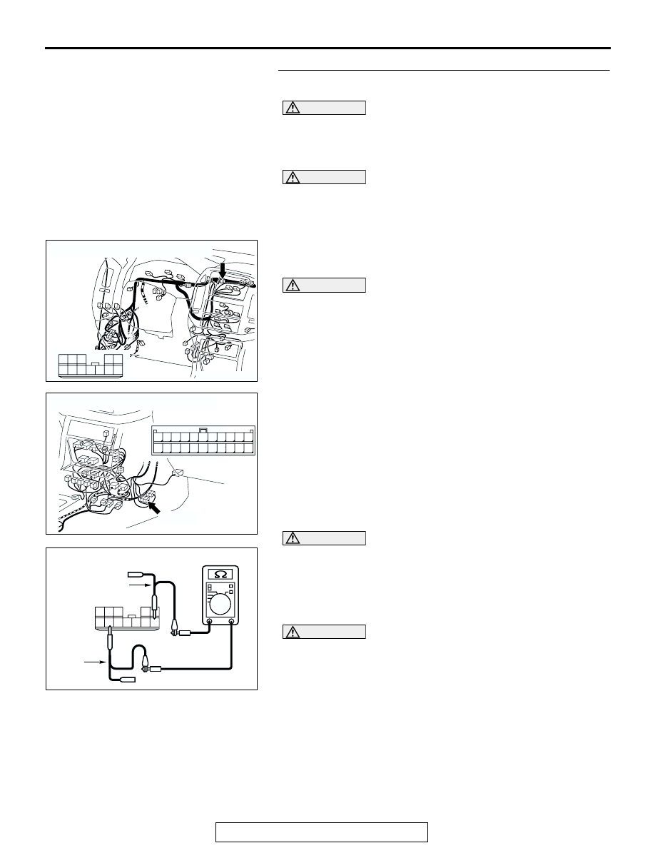
STEP 28. Check the CAN bus line for short circuit. Measure at
joint connector (9) D-131.
CAUTION
Before checking CAN bus lines and their interconnected compo-
nents, "ground" yourself, by touching a metal object such as an
unpainted pipe, this will discharge any potentially damaging
static that may have built up.
CAUTION
When measuring resistance value or voltage in CAN bus lines,
use a digital multimeter. If not using a digital multimeter, the
equipments, which are connected through the CAN communica-
tion lines, may be damaged.
(1) Disconnect joint connector (9) D-131 and intermediate connector
E-122, and measure the resistance at joint connector (9).
(2) Turn the ignition switch to the LOCK (OFF) position.
CAUTION
Disconnect the negative battery terminal when measuring the
resistance value in the CAN bus line. If you fail to do so, the
equipments, which are connected through the CAN communica-
tion lines, may be damaged.
(3) Disconnect the negative battery terminal.
CAUTION
Always use the test harness when measuring the voltage or
resistance value at the female connector. If you fail to do so,
connectors may be damaged.
(4) Measure the resistance between joint connector (9) D-131
terminals 6 and 11.
• The resistance should be infinite.
CAUTION
If you repair the CAN bus line of the instrument panel wiring har-
ness assembly (the wiring harness connected to the steering
wheel sensor, the data link connector and the resistor) and the
transmission wiring harness assembly (the wiring harness con-
nected to the G and yaw rate sensor connector and intermediate
connector E-123), observe the precautions regarding how to
repair wiring harness. If a new wire is added or a splice point is
modified for the CAN_L or CAN_H line, an error in the CAN com-
munication may be caused.
Q: Is the resistance infinite?
YES : Retest the system.
NO : Repair the wiring harness wires between joint connector (9)
and the intermediate connector.
AC204170
CONNECTOR: D-131
AT
6
1
9 8
2
7
10
12 11
4
5
3
AC204176
CONNECTOR: E-122
E-122(L)
MALE SIDE
E-122(L)
AF
1
12
2
13
3
14
4
15
5
16
6
17
7
18
8
19
9
20
10
21
11
22
AC204738
HARNESS SIDE: D-131
TEST
HARNESS
EN
6
1
9 8
2
7
10
12 11
4
5
3
TEST
HARNESS