Mitsubishi Montero (2002-2004). Manual - part 1133


  Index      Mitsubishi     Mitsubishi Montero - service repair manual 2002-2004 year


Search            


Content   ..  1131  1132  1133  1134   ..


Mitsubishi Montero (2002-2004). Manual - part 1133


M-ASTC DIAGNOSIS

TSB Revision

MITSUBISHI ACTIVE SKID AND TRACTION CONTROL SYSTEM

35C-149

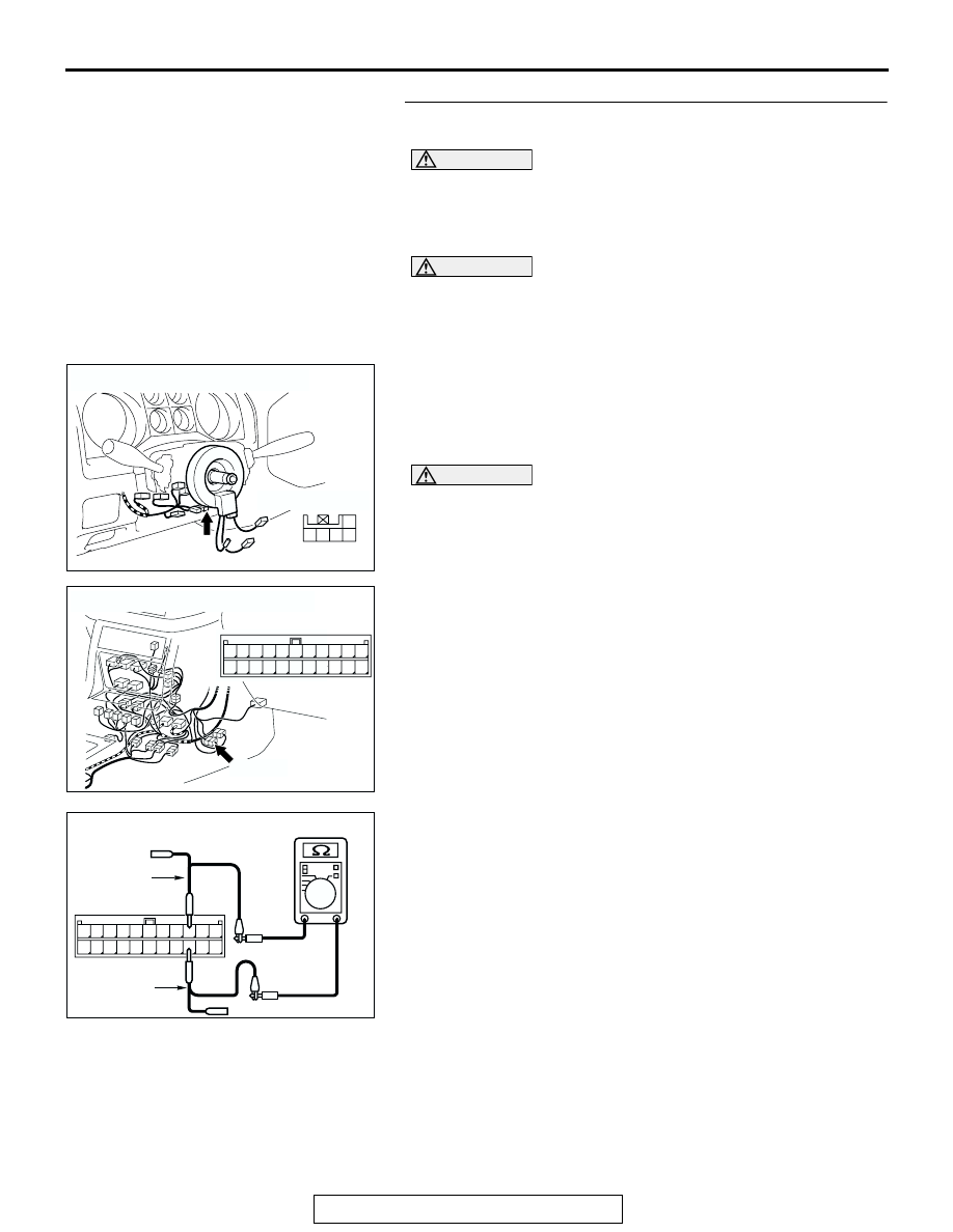
STEP 24. Check for short circuit at the resistor. Check at 
intermediate connector E-122.

CAUTION

Before checking CAN bus lines and their interconnected 
components, "ground" yourself, by touching a metal 
object such as an unpainted pipe, this will discharge any 
potentially damaging static that may have built up.

CAUTION

When measuring resistance value or voltage in CAN bus 
lines, use a digital multimeter. If not using a digital multim-
eter, the equipments, which are connected through the 
CAN communication lines, may be damaged.
(1) Disconnect intermediate connector E-122 and steering 

wheel sensor connector D-225, and measure the resistance 
at the male intermediate connector (instrument panel wiring 
harness side).

(2) Turn the ignition switch to the LOCK (OFF) position.

CAUTION

Disconnect the negative battery terminal when measuring 
the resistance value in the CAN bus line. If you fail to do 
so, the equipments, which are connected through the CAN 
communication lines, may be damaged.
(3) Disconnect the negative battery terminal.

(4) Measure the resistance between intermediate connector E-

122 terminals 9 and 20.

• The resistance should measure 120 ± 12 ohms.

Q: Does the resistance measure 120 

± 12 ohms?

YES : Go to Step 29.
NO :  Go to Step 25.

AC204172

CONNECTOR: D-225

HARNESS SIDE

AD

3 2

1

4

5

AC204176

CONNECTOR: E-122

E-122(L)

MALE SIDE

E-122(L)

AF

1

12

2

13

3

14

4

15

5

16

6

17

7

18

8

19

9

20

10

21

11

22

AC204581

MALE CONNECTOR: E-122

TEST 
HARNESS

AC

TEST 
HARNESS

1

12

2

13

3

14

4

15

5

16

6

17

7

18

8

19

9

20

10

21

11

22

M-ASTC DIAGNOSIS

TSB Revision

MITSUBISHI ACTIVE SKID AND TRACTION CONTROL SYSTEM

35C-150

STEP 25. Check the CAN bus line for short circuit. Measure at 
joint connector (9) D-131.

CAUTION

Before checking CAN bus lines and their interconnected compo-
nents, "ground" yourself, by touching a metal object such as an 
unpainted pipe, this will discharge any potentially damaging 
static that may have built up.

CAUTION

When measuring resistance value or voltage in CAN bus lines, 
use a digital multimeter. If not using a digital multimeter, the 
equipments, which are connected through the CAN communica-
tion lines, may be damaged.
(1) Disconnect joint connector (9) D-131, and measure the resistance 

at joint connector (9).

(2) Turn the ignition switch to the LOCK (OFF) position.

CAUTION

Disconnect the negative battery terminal when measuring the 
resistance value in the CAN bus line. If you fail to do so, the 
equipments, which are connected through the CAN communica-
tion lines, may be damaged.
(3) Disconnect the negative battery terminal.

CAUTION

Always use the test harness when measuring the voltage or 
resistance value at the female connector. If you fail to do so, 
connectors may be damaged.
(4) Measure the resistance between joint connector (9) D-131 

terminals 7 and 12.

• The resistance should be infinite.

CAUTION

If you repair the CAN bus line of the instrument panel wiring har-
ness assembly (the wiring harness connected to the steering 
wheel sensor, the data link connector and the resistor) and the 
transmission wiring harness assembly (the wiring harness con-
nected to the G and yaw rate sensor connector and intermediate 
connector E-123), observe the precautions regarding how to 
repair wiring harness. If a new wire is added or a splice point is 
modified for the CAN_L or CAN_H line, an error in the CAN com-
munication may be caused.
Q: Is the resistance infinite?

YES :  Go to Step 26.
NO :  Repair the wiring harness wires between joint connector (9) 

and the data link connector.

AC204188

CONNECTORS: D-117, D-131

D-131

BF

HARNESS SIDE

HARNESS SIDE

D-131

D-117

D-117

6

1

9 8

2

7

10

12 11

4

5

3

21

26

22

27 2829 30

23

31

24

32

25

33

AC204738

HARNESS SIDE: D-131

TEST 
HARNESS

EL

6

1

9 8

2

7

10

12 11

4

5

3

TEST 
HARNESS

M-ASTC DIAGNOSIS

TSB Revision

MITSUBISHI ACTIVE SKID AND TRACTION CONTROL SYSTEM

35C-151

STEP 26. Check the CAN bus line for short circuit. Measure at 
joint connector (9) D-131.

CAUTION

Before checking CAN bus lines and their interconnected compo-
nents, "ground" yourself, by touching a metal object such as an 
unpainted pipe, this will discharge any potentially damaging 
static that may have built up.

CAUTION

When measuring resistance value or voltage in CAN bus lines, 
use a digital multimeter. If not using a digital multimeter, the 
equipments, which are connected through the CAN communica-
tion lines, may be damaged.
(1) Disconnect joint connector (9) D-131 and resistor connector D-

130, and measure the resistance at joint connector (9).

(2) Turn the ignition switch to the LOCK (OFF) position.

CAUTION

Disconnect the negative battery terminal when measuring the 
resistance value in the CAN bus line. If you fail to do so, the 
equipments, which are connected through the CAN communica-
tion lines, may be damaged.
(3) Disconnect the negative battery terminal.

CAUTION

Always use the test harness when measuring the voltage or 
resistance value at the female connector. If you fail to do so, 
connectors may be damaged.
(4) Measure the resistance between joint connector (9) D-131 

terminals 1 and 4.

• The resistance should be infinite.

CAUTION

If you repair the CAN bus line of the instrument panel wiring har-
ness assembly (the wiring harness connected to the steering 
wheel sensor, the data link connector and the resistor) and the 
transmission wiring harness assembly (the wiring harness con-
nected to the G and yaw rate sensor connector and intermediate 
connector E-123), observe the precautions regarding how to 
repair wiring harness. If a new wire is added or a splice point is 
modified for the CAN_L or CAN_H line, an error in the CAN com-
munication may be caused.
Q: Is the resistance infinite?

YES :  Go to Step 27.
NO :  Repair the wiring harness wires between joint connector (9) 

and the resistor connector.

AC204188

CONNECTORS: D-130, D-131

D-131

AQ

HARNESS SIDE

HARNESS SIDE

D-131

D-130

D-130

6

1

9 8

2

7

10

12 11

4

5

3

1
2

AC204738

HARNESS SIDE: D-131

TEST 
HARNESS

EO

6

1

9 8

2

7

10

12 11

4

5

3

TEST 
HARNESS

M-ASTC DIAGNOSIS

TSB Revision

MITSUBISHI ACTIVE SKID AND TRACTION CONTROL SYSTEM

35C-152

STEP 27. Check the CAN bus line for short circuit. Measure at 
joint connector (9) D-131.

CAUTION

Before checking CAN bus lines and their interconnected compo-
nents, "ground" yourself, by touching a metal object such as an 
unpainted pipe, this will discharge any potentially damaging 
static that may have built up.

CAUTION

When measuring resistance value or voltage in CAN bus lines, 
use a digital multimeter. If not using a digital multimeter, the 
equipments, which are connected through the CAN communica-
tion lines, may be damaged.
(1) Disconnect joint connector (9) D-131 and steering wheel sensor 

connector D-225, and measure the resistance at joint connector 
(9).

(2) Turn the ignition switch to the LOCK (OFF) position.

CAUTION

Disconnect the negative battery terminal when measuring the 
resistance value in the CAN bus line. If you fail to do so, the 
equipments, which are connected through the CAN communica-
tion lines, may be damaged.
(3) Disconnect the negative battery terminal.

CAUTION

Always use the test harness when measuring the voltage or 
resistance value at the female connector. If you fail to do so, 
connectors may be damaged.
(4) Measure the resistance between joint connector (9) D-131 

terminals 2 and 5.

• The resistance should be infinite.

CAUTION

If you repair the CAN bus line of the instrument panel wiring har-
ness assembly (the wiring harness connected to the steering 
wheel sensor, the data link connector and the resistor) and the 
transmission wiring harness assembly (the wiring harness con-
nected to the G and yaw rate sensor connector and intermediate 
connector E-123), observe the precautions regarding how to 
repair wiring harness. If a new wire is added or a splice point is 
modified for the CAN_L or CAN_H line, an error in the CAN com-
munication may be caused.
Q: Is the resistance infinite?

YES :  Go to Step 28.
NO :  Repair the wiring harness wires between joint connector (9) 

and the steering wheel sensor connector.

AC204188

CONNECTORS: D-130, D-131

D-131

AQ

HARNESS SIDE

HARNESS SIDE

D-131

D-130

D-130

6

1

9 8

2

7

10

12 11

4

5

3

1
2

AC204738

HARNESS SIDE: D-131

TEST 
HARNESS

EM

6

1

9 8

2

7

10

12 11

4

5

3

TEST 
HARNESS


Content   ..  1131  1132  1133  1134   ..