Mitsubishi Montero (2002-2004). Manual - part 1107


  Index      Mitsubishi     Mitsubishi Montero - service repair manual 2002-2004 year


Search            


Content   ..  1105  1106  1107  1108   ..


Mitsubishi Montero (2002-2004). Manual - part 1107


M-ASTC DIAGNOSIS

TSB Revision

MITSUBISHI ACTIVE SKID AND TRACTION CONTROL SYSTEM

35C-45

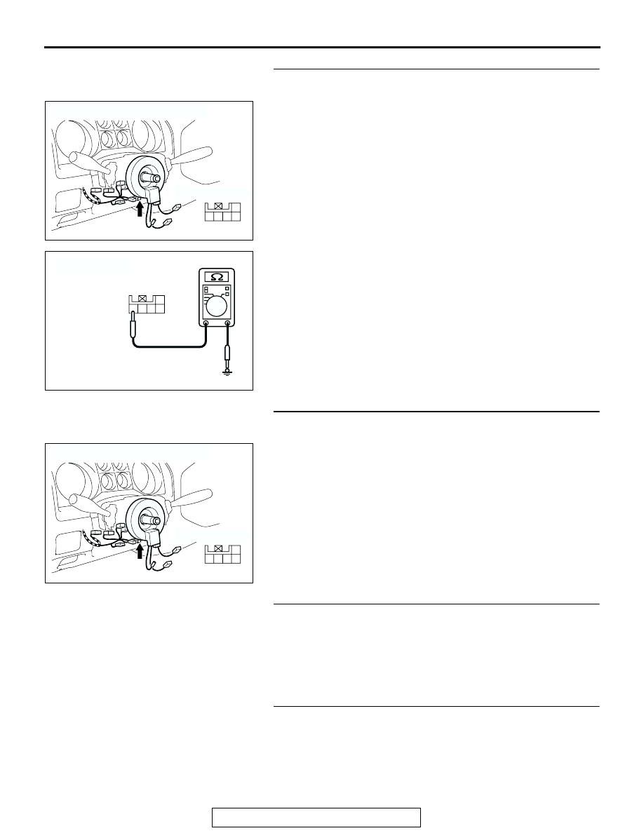
STEP 8. Check the steering wheel sensor for ground 
circuit. Measure at steering wheel sensor connector D-225.
(1) Disconnect steering wheel sensor connector D-225, and 

measure the resistance at the harness-side connector.

(2) Measure the resistance between steering wheel sensor 

connector D-225 terminal 5 and body ground.

• The resistance should measure 2 ohms or less.

Q: Does the resistance measure 2 ohms or less?

YES : Go to Step 10.
NO :  Go to Step 9.

STEP 9. Check the wiring harness between steering wheel 
sensor connector D-225 terminal 5 and the body ground.
Q: Is the wiring harness between steering wheel sensor 

connector D-225 terminal 5 and the body ground in 
good condition?
YES : 
Go to Step 11.
NO :  Repair the wiring harness, and then go to Step 11.

STEP 10. Replace the steering wheel sensor.
Replace the steering wheel sensor, and check that the DTC 
sets.
Q: Does the M-ASTC-ECU set any DTC?

YES : Replace the M-ASTC-ECU, and then go to Step 11.
NO :  The procedure is complete.

STEP 11. Recheck for diagnostic trouble code.
Q: Does DTC 67 reset?

YES : Return to Step 1.
NO :  The procedure is complete.

AC204172

CONNECTOR: D-225

HARNESS SIDE

AD

3 2

1

4

5

AC204581

3 2

1

4

5

HARNESS SIDE: D-225

AV

AC204172

CONNECTOR: D-225

HARNESS SIDE

AD

3 2

1

4

5

M-ASTC DIAGNOSIS

TSB Revision

MITSUBISHI ACTIVE SKID AND TRACTION CONTROL SYSTEM

35C-46

DTC 74: Communication error in G and yaw rate sensor

CAUTION

If the diagnostic trouble code(s), which indicate a 
communication error in the G and yaw rate sen-
sor, has been set, diagnose the CAN main bus 
line.

AC205075

G and Yaw Rate Sensor Communication Circuit

AB

AC204170

CONNECTOR: D-01

AY

AC204173

CONNECTORS: D-208, D-212

D-208

D-212

AX

M-ASTC DIAGNOSIS

TSB Revision

MITSUBISHI ACTIVE SKID AND TRACTION CONTROL SYSTEM

35C-47

.

CIRCUIT OPERATION
The M-ASTC-ECU gathers information regarding lat-
eral and longitudinal gravities and yaw rate, through 
the CAN bus line from the G and yaw rate sensor.

.

M-ASTC DTC SET CONDITION
DTC 74 is set if the M-ASTC-ECU cannot gather any 
information from the G and yaw rate sensor.

.

TROUBLESHOOTING HINTS
The most likely causes for DTC 74 to set are:

• The CAN bus line is defective.

• Damaged connector(s)

• The G and yaw rate sensor is defective.

• The M-ASTC-ECU is defective.

DIAGNOSIS 

Required Special Tools:

• MB991223: Harness Set

• MB991502: Scan Tool (MUT-II)

STEP 1. CAN main bus line diagnostics

CAUTION

If DTC 74 is set, diagnose the CAN main bus line.
Diagnose the CAN main bus line. Refer to 

P.35C-60

.

Q: Have you completed checking or repairing the CAN 

main bus line?
YES : 

• If the CAN main bus line is repaired, go to Step 9 .

• If the CAN main bus line is not defective, go to 

Step 2.

NO :  Diagnose the CAN main bus line. Refer to 

P.35C-60

.

AC204176

CONNECTOR: E-111

AK

AC204175

CONNECTOR: E-126

AD

E-126(GR)

FLOOR 
CONSOLE

M-ASTC DIAGNOSIS

TSB Revision

MITSUBISHI ACTIVE SKID AND TRACTION CONTROL SYSTEM

35C-48

STEP 2. Using scan tool MB991502, check data list items 
27, 28 and 29.
(1) Confirm that the vehicle is not canted to one side or corner.

CAUTION

To prevent damage to scan tool MB991502, always turn the 
ignition switch to the "LOCK" (OFF) position before con-
necting or disconnecting scan tool MB991502.
(2) Connect scan tool MB991502 to the data link connector 

(16-pin).

(3) Turn the ignition switch to the "ON" position.
(4) Check that the G and yaw rate sensor output signal is 

approximately 0 m/s

2

.

(5) When the G and yaw rate sensor is inclined, the readings 

on data list items 27, 28 and 29 should change.

Q: When the G and yaw rate sensor is inclined, do the 

readings on data list items 27, 28 and 29 change?
YES : 
Go to Step 8.
NO :  Go to Step 3.

STEP 3. Check G and yaw rate sensor connector E-126.
Q: Is G and yaw rate sensor connector E-126 in good 

condition?
YES : 
Go to Step 4.
NO :  Repair or replace the connector, and then go to Step 

10.

AC204175

CONNECTOR: E-126

HARNESS SIDE

E-126(GR)

E-126(GR)

AB

FLOOR 
CONSOLE

1

2

4 3


Content   ..  1105  1106  1107  1108   ..