Mitsubishi Montero (2002-2004). Manual - part 1100


  Index      Mitsubishi     Mitsubishi Montero - service repair manual 2002-2004 year


Search            


Content   ..  1098  1099  1100  1101   ..


Mitsubishi Montero (2002-2004). Manual - part 1100


M-ASTC DIAGNOSIS

TSB Revision

MITSUBISHI ACTIVE SKID AND TRACTION CONTROL SYSTEM

35C-17

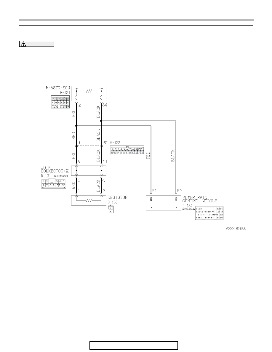
DTC 36, 38: Communication error in power control module

CAUTION

If the diagnostic trouble code(s), which indicate a 
communication error in the power control mod-
ule, has been set, diagnose the CAN main bus 
line.

.

CIRCUIT OPERATION
The M-ASTC-ECU gathers information regarding the 
engine and automatic transmission, through the CAN 
bus line from the power control module.

.

M-ASTC DTC SET CONDITION
DTC 36 is set if the M-ASTC-ECU cannot gather all 
information regarding the engine from the PCM. DTC 
38 is set if the ECU cannot gather all information 
regarding the automatic transmission from the PCM.

.

TROUBLESHOOTING HINTS
The most likely causes for DTC 36, 38 to set are:

• The CAN bus line is defective.

• Damaged connector(s)

• The power control module is defective

• The M-ASTC-ECU is defective.

AC205062

CAN Bus Communication Circuit (powertrain control module)

AB

M-ASTC DIAGNOSIS

TSB Revision

MITSUBISHI ACTIVE SKID AND TRACTION CONTROL SYSTEM

35C-18

DIAGNOSIS 

Required Special Tools:

• MB991223: Harness Set

• MB991502: Scan Tool (MUT-II)

STEP 1. CAN main bus line diagnostics

CAUTION

If DTC 36 or 38 is set, diagnose the CAN main bus line.
Diagnose the CAN main bus line. Refer to 

P.35C-60

.

If the CAN main bus line is repaired, check that the diagnostic 
trouble code resets.
Q: Have you completed checking or repairing the CAN 

main bus line?
YES : 

• If the CAN main bus line is repaired, go to Step 3 .

• If the CAN main bus line is not defective, go to 

Step 2.

NO :  Diagnose the CAN main bus line. Refer to 

P.35C-60

.

STEP 2. Check for engine and automatic transmission 
DTCs.
Check whether engine and automatic transmission DTCs are 
set or not.
Q: Are engine and automatic transmission DTCs set?

YES : Diagnose the power control module. Refer to 

P.13Ab-

22

.

NO :  Replace the M-ASTC-ECU, and then go to Step 3.

STEP 3. Recheck for diagnostic trouble code.
Q: Does DTC 36 or 38 reset?

YES : Return to Step 1.
NO :  The procedure is complete.

M-ASTC DIAGNOSIS

TSB Revision

MITSUBISHI ACTIVE SKID AND TRACTION CONTROL SYSTEM

35C-19

DTC 47: Defective Cut Valve
DTC 48: Defective Pressure-increase Valve

.

CIRCUIT OPERATION
As the ignition switch is turned ON, power is supplied 
to each solenoid valve via the valve relay. M-ASTC-
ECU, by turning ON the transistor, grounds the circuit 
and turns the solenoid valve ON.

.

M-ASTC DTC SET CONDITIONS
The M-ASTC-ECU constantly monitors the solenoid 
valve drive circuits. These codes are output if the M-
ASTC-ECU judges that there is an open circuit or 
short-circuit in a solenoid coil or harness because the 
solenoid valve is on but no current flows to the sole-
noid valve, or if current continues flowing to the sole-
noid valve even though the solenoid valve is off.

.

AC205065

Cut Valve and PI Valve Circuit

AB

AC204169 AC

CONNECTORS: B-14, B-18

B-14(B)

B-18(B)

AC204176

CONNECTOR: E-119

AN

M-ASTC DIAGNOSIS

TSB Revision

MITSUBISHI ACTIVE SKID AND TRACTION CONTROL SYSTEM

35C-20

TROUBLESHOOTING HINTS (The most likely 
causes for these DTCs to set are:)

• The hydraulic brake booster (HBB) is defective.

• Damaged harness wires and connectors

• The M-ASTC-ECU is defective.

DIAGNOSIS

Required Special Tools:

• MB991223: Harness Set

• MB991502: Scan Tool (MUT-II)

STEP 1. Check for M-ASTC DTC.
Check that the M-ASTC-ECU sets any other DTCs than 47 or 
48.
Q: Does the M-ASTC-ECU set any other DTCs than 47 or 

48?
YES : 
First diagnose the other DTCs.
YES : Go to Step 2.

STEP 2. Check the solenoid valve drive circuit. Measure at 
M-ASTC-ECU connector E-119 by backprobing.
(1) Measure the voltage by backprobing (i.e. without 

disconnecting M-ASTC-ECU connector E-119). 

(2) Turn the ignition switch to the "ON" position.
(3) Measure voltage between the following terminals. It should 

be approximately 12 volts (battery positive voltage).

When DTC 47 is set:

• M-ASTC-ECU connector E-119 terminal 6 and ground

•The voltage should measure battery voltage (approxi-

mately 12 volts).

When DTC 48 is set:

• M-ASTC-ECU connector E-119 terminal 5 and ground

• The voltage should measure battery voltage (approxi-

mately 12 volts).

Q: Does the voltage measure battery voltage 

(approximately 12 volts)?
YES : 
Go to Step 3.
NO :  Go to Step 4.

AC204176

CONNECTOR: E-119

HARNESS 
SIDE

AJ

9

8

21 20

31 30

7

6

5

4

3

2 1

18

28

1716

13

27

15

25

14

26

12

24

11

23

10

22

19

29

AC204580

COMPONENT SIDE: E-119

AQ

1 2

10 11

22 23

3

4

5

6

7

8

9

13

25

1415

18

26

16

27

17

28

19

29

20

30

21

31

12

24

AC204580

COMPONENT SIDE: E-119

AP

1 2

10 11

22 23

3

4

5

6

7

8

9

13

25

1415

18

26

16

27

17

28

19

29

20

30

21

31

12

24


Content   ..  1098  1099  1100  1101   ..