Mitsubishi Montero (2002-2004). Manual - part 84


  Index      Mitsubishi     Mitsubishi Montero - service repair manual 2002-2004 year


Search            


Content   ..  82  83  84  85   ..


Mitsubishi Montero (2002-2004). Manual - part 84


AUTO A/C DIAGNOSIS

TSB Revision

AUTOMATIC AIR CONDITIONING

55B-29

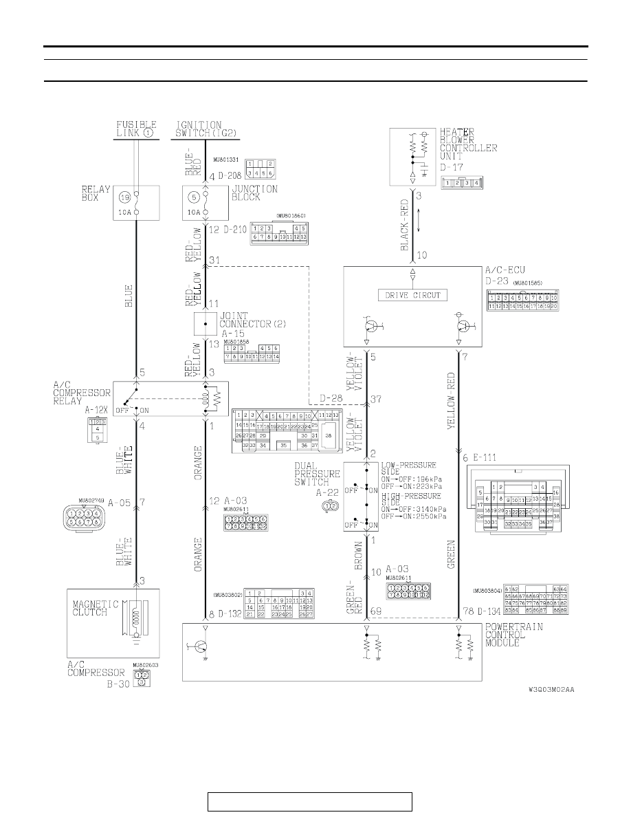
INSPECTION PROCEDURE 2: Air Conditioning does not Operate.

A/C Compressor Circuit

AUTO A/C DIAGNOSIS

TSB Revision

AUTOMATIC AIR CONDITIONING

55B-30

.

TECHNICAL DESCRIPTION (COMMENT)
If cool air is not distributed when the A/C switch is on, 
the air thermo sensor or the A/C compressor relay 
system may be defective. 

.

AC204167

CONNECTORS : A-03, A-05, 
A-15, A-22

BA

A-03(B)

A-05(B)

A-15

A-22(BR)

AC204183

CONNECTOR : A-12X

AQ

AC204169

CONNECTOR : B-30

AF

B-30(B)

AC204171BD

D-134(GR)

D-17

D-132(GR)

CONNECTORS : D-17, D-132, D-134

AC204170

CONNECTORS : D-23, D-28

DW

D-28

D-23(B)

AC204173

CONNECTORS : D-208, D-210

BF

D-208

D-210

AC204176 BM

CONNECTOR : E-111

AUTO A/C DIAGNOSIS

TSB Revision

AUTOMATIC AIR CONDITIONING

55B-31

TROUBLESHOOTING HINTS

• Malformation of the air thermo sensor 

• Malformation of the dual pressure switch

• Malformation of the A/C compressor relay

• Malformation of the A/C refrigerant temperature 

switch

• Malformation of the magnetic clutch

• Malformation of the A/C-ECU

• Malformation of the flexible flat cable

• Malformation of the automatic air-conditioning 

control panel

• Malformation of the PCM

DIAGNOSIS

Required Special Tools:

• MB991223: Test Harness Set

• MB991502: Scan Tool

STEP 1. Using scan tool MB991502, read the diagnostic 
trouble code.
Q: Is a diagnostic trouble code set?

YES : Refer to 

P.55B-5

.

NO :   Go to Step 2.

STEP 2. Check the defogger and outside/inside air 
changeover damper control motor operation.
Q: Do the defogger and outside/inside air changeover 

damper control motor work normally?
YES : 
Go to Step 3.
NO :  Refer to Inspection Procedure 11 "Malfunction does 

not operate 

P.55B-118

."

STEP 3. Check the blower motor operation.
Q: Does the blower motor work normally?

YES : Go to Step 4.
NO :  Refer to Inspection Procedure 5 "Blower Fan and 

motor does not tern 

P.55A-12

."

STEP 4. Check the refrigerant level.
Q: Is the refrigerant level correct?

YES : Go to Step 5.
NO :  Correct the refrigerant level. (Refer to On-vehicle 

Service 

P.55A-118

) Check that the air conditioning 

works normally. 

AUTO A/C DIAGNOSIS

TSB Revision

AUTOMATIC AIR CONDITIONING

55B-32

STEP 5. Check the A/C compressor relay continuity.
Follow the table below to check the A/C compressor relay for 
continuity.

Q: Is the A/C compressor relay in good condition?

YES : Go to Step 6.
NO :  Replace the A/C compressor relay. Check that the air 

conditioning works normally. 

STEP 6. Measure the voltage at A/C compressor connector 
B-30.
(1) Disconnect A/C compressor connector B-30 and measure 

the voltage at the harness side.

(2) Turn the ignition switch to the "ON" position.
(3) Turn the A/C switch to the "ON" position.
(4) Turn the blower switch to the "ON" position.

(5) Measure the voltage between terminal 3 and ground.

• The measured value should be approximately 12 volts 

(battery positive voltage).

Q: Does the measured voltage correspond with this range?

YES :  Go to Step 7.
NO :   Go to Step 8.

BATTERY VOLTAGE

TESTER 
CONNECTION 

SPECIFIED 
CONDITION

Not applied

− 5

Open circuit

• Connect terminal 3 to 

the positive battery 
terminal

• Connect terminal 1 to 

the negative battery 
terminal

− 5

Less than 2 
ohms

AC204715

3

1

4

5

AB

A/C 
COMPRESSOR 
RELAY

BATTERY

AC204169

CONNECTOR : B-30

AE

B-30(B)

B-30(B)

2

3

1

HARNESS 
SIDE

AC204738 CY

HARNESS SIDE : B-30

2

3

1


Content   ..  82  83  84  85   ..