Mitsubishi Montero (2002-2004). Manual - part 82


  Index      Mitsubishi     Mitsubishi Montero - service repair manual 2002-2004 year


Search            


Content   ..  80  81  82  83   ..


Mitsubishi Montero (2002-2004). Manual - part 82


AUTO A/C DIAGNOSIS

TSB Revision

AUTOMATIC AIR CONDITIONING

55B-21

STEP 5. Recheck for diagnostic trouble code.
Q: Is DTC 31 set?

YES :  Return to Step 1.
NO :  The procedure is complete.

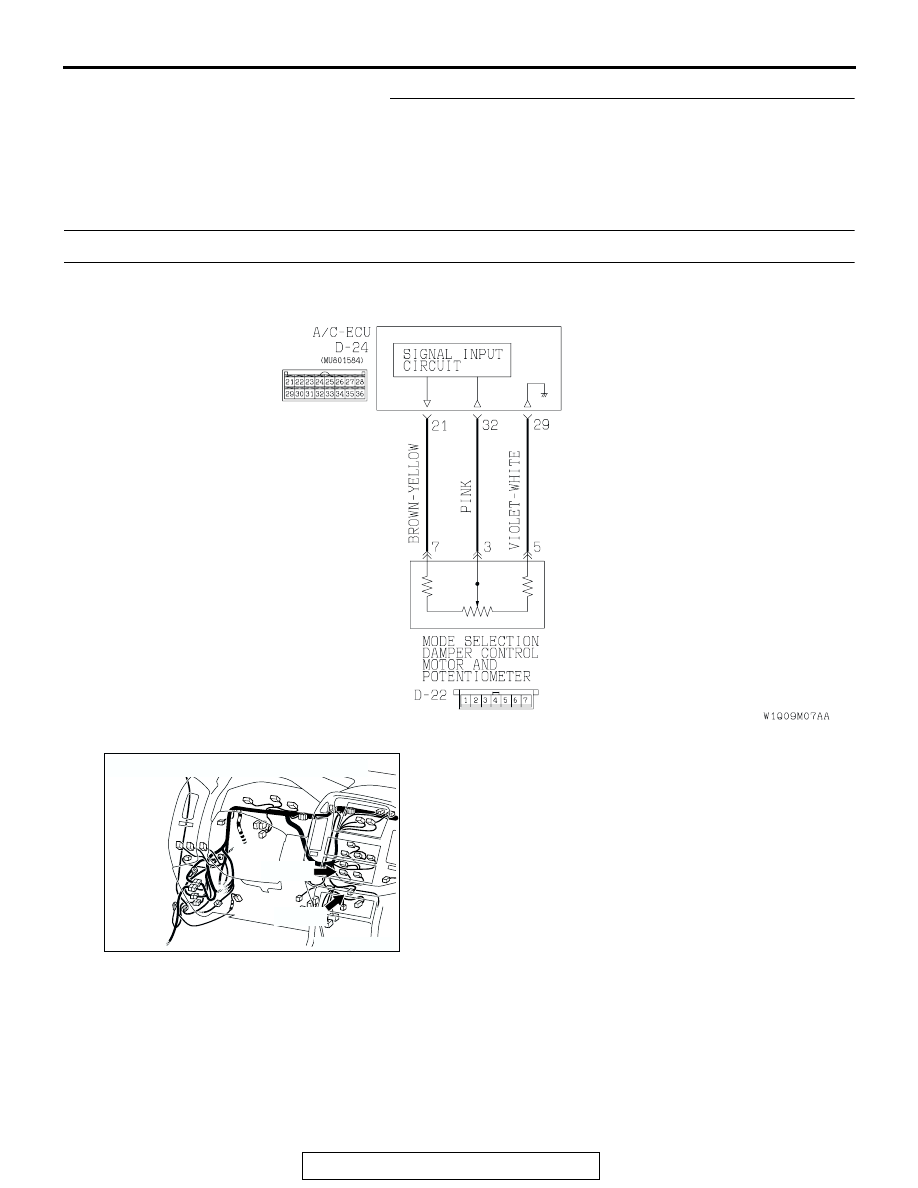
DTC 32: Potentiometer System of Air Outlet Changeover Damper Control Motor Assembly.

DTC SET CONDITION

• DTC 32 is output if there is an open or short cir-

cuit in the potentiometer input circuit, or if there is 
an open circuit in the power circuit or earth circuit.

TROUBLESHOOTING HINT

• Malfunction of connector.

• Malfunction of the harness.

• Malfunction of the mode selection damper control 

motor and potentiometer.

• Malfunction of the A/C-ECU.

Air Outlet Changeover Damper Potentiometer Circuit

AC205351

AC204170

CONNECTORS : D-22, D-24

DU

D-24(B)

D-22(B)

AUTO A/C DIAGNOSIS

TSB Revision

AUTOMATIC AIR CONDITIONING

55B-22

STEP 1. Using scan tool MB991502, check data list item 32: 
Mode selection damper control motor and potentiometer.
Check the data list. 
Item 32: mode selection damper control motor and potentiome-
ter 
Q: Does the data list show approximately 0% (at FACE 

position), approximately 60% (at FOOT position), 
approximately 80% (at FOOT/DEF position), and 
approximately 100% (at DEF position)?
YES : 
 It can be assumed that this malfunction is 

intermittent. (Refer to GROUP 00 - How to Cope with 
Intermittent Malfunction 

P.00-6

.) 

NO :   Go to Step 2.

STEP 2. Check the mode selection damper control motor 
and potentiometer.

CAUTION

Do not apply battery voltage when the damper is in the 
FACE or DEF position.
Check the mode selection damper control motor by the follow-
ing procedures.

While checking the mode selection damper control motor, mea-
sure the resistances between terminal Nos. 3 and 5 as well as 
terminal Nos. 3 and 7. At this time, the resistances should 
change gradually within the standard value.

Standard value: 0.96 

 5.76 k ohms

Q: Does mode selection damper control motor and 

potentiometer work normally?
YES : 
Go to Step 3.
NO :  Replace the mode selection damper control motor 

and potentiometer. Then go to Step 5.

LEVER POSITION BATTERY 

CONNECTION

LEVER 
OPERATION

At the DEF position

• Connect 

terminal 1 to the 
positive battery 
terminal

• Connect 

terminal 2 to the 
negative battery 
terminal

The lever moves 
from the DEF 
position to the 
outside position

At the FACE 
position

• Connect 

terminal 2 to the 
positive battery 
terminal

• Connect 

terminal 1 to the 
negative battery 
terminal

The lever moves 
from the FACE 
position to the 
inside position

ACX01457

FACE POSITION

DEF POSITION

AB

AUTO A/C DIAGNOSIS

TSB Revision

AUTOMATIC AIR CONDITIONING

55B-23

STEP 3. Check mode selection damper control motor and 
potentiometer connector D-22 and A/C-ECU connector D-
24 for damage.
Q: Is mode selection damper control motor and 

potentiometer connector D-22 and A/C-ECU connector 
D-24 in good condition?
YES : 
Go to Step 4.
NO :  Repair or replace the connector. Refer to GROUP 

00E, Harness Connector Inspection 

P.00E-2

. Then go 

to Step 5.

STEP 4. Check the wiring harness between mode selection 
damper control motor and potentiometer connector D-22 
(terminals 7, 3 and 5) and A/C-ECU D-24 (terminals 21, 32 
and 29).
Q: Is the wiring harness between mode selection damper 

control motor and potentiometer connector D-22 
(terminals 7, 3 and 5) and A/C-ECU D-24 (terminals 21, 
32 and 29) in good condition?
YES : 
Replace the A/C-ECU. (Refer to 

P.55B-136

.) Then go 

to Step 5.

NO :  Repair the wiring harness. Then go to Step 5.

AC204188

CONNECTORS : D-22, D-24

D-24(B)

D-24(B)

CA

D-22(B)

D-22(B)

HARNESS SIDE

HARNESS SIDE

22

23

30

31

25

26

33

34

32

24

28

3635

27

29

21

7 6 5 4 3 2 1

AC204188

CONNECTORS : D-22, D-24

D-24(B)

D-24(B)

CA

D-22(B)

D-22(B)

HARNESS SIDE

HARNESS SIDE

22

23

30

31

25

26

33

34

32

24

28

3635

27

29

21

7 6 5 4 3 2 1

AUTO A/C DIAGNOSIS

TSB Revision

AUTOMATIC AIR CONDITIONING

55B-24

STEP 5. Recheck for diagnostic trouble code.
Q: Is DTC 32 set?

YES :  Return to Step 1.
NO :  The procedure is complete.

SYMPTOM PROCEDURES

INSPECTION PROCEDURE 1: Communication with the scan tool is not Possible.

TECHNICAL DESCRIPTION
The harness wires between the A/C-ECU power sup-
ply line or the A/C-ECU and the data link connector 
may be defective.

TROUBLESHOOTING HINT

• Malfunction of connector.

• Malfunction of the harness.

• Malfunction of the A/C-ECU.

Data Link Connector Circuit

AC204170

CONNECTORS : D-23, D-24, D-28, D-118

D-23(B)

D-24(B)

D-28

EH

D-118(B)

AC204173

CONNECTORS : D-210, D-211

D-210

D-211(B)

AU


Content   ..  80  81  82  83   ..