Mitsubishi Montero (2002-2004). Manual - part 63


  Index      Mitsubishi     Mitsubishi Montero - service repair manual 2002-2004 year


Search            


Content   ..  61  62  63  64   ..


Mitsubishi Montero (2002-2004). Manual - part 63


REAR AIR CONDITIONING DIAGNOSIS

TSB Revision

HEATER, AIR CONDITIONING AND VENTILATION

55A-115

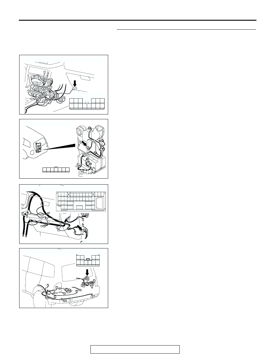
STEP 11. Check the wiring harness between rear A/C 
control unit connector E-20 (terminal 9, 10 and 11) and 
mode selection damper control motor connector G-22-3 
(terminal 6, 4 and 3).

NOTE: Also check intermediate connector D-112 and rear A/C 
unit connector G-22. If intermediate connector D-112 and rear 
A/C unit connector G-22 is damaged, repair or replace the con-
nector as described in GROUP 00E, Harness Connector 
Inspection 

P.00E-2

.

Q: Is the wiring harness between rear A/C control unit 

connector E-20 (terminal 9, 10 and 11) and mode 
selection damper control motor connector G-22-3 
(terminal 6, 4 and 3) in good condition?
YES : 
Go to Step 12.
NO :  Repair the wiring harness. Check that the rear air 

conditioning works normally.

AC204176

CONNECTOR : E-20

AY

HARNESS SIDE

7

8

3

10 9

2

4

11

1312

5

14

6

1

AC204698

CONNECTOR : G-22-3

AG

HARNESS SIDE

7 6 5 4 3 2 1

AC204171 AL

CONNECTOR : D-112

2 3

27

32

28

33

16

15

4 5

19

18

29

17

34

7 8

35

22

21

9 10

30

36

31

37

25

24

23

6

20

1

14

26

11

13

12

38

AC204179

CONNECTOR : G-22

AP

HARNESS SIDE

1

5

7

8

2

6

10

4

9

3

REAR AIR CONDITIONING DIAGNOSIS

TSB Revision

HEATER, AIR CONDITIONING AND VENTILATION

55A-116

STEP 12. Replace the mode selection damper control 
motor connector.
Q: Do the air conditioning work normally?

YES : No action is necessary and testing is complete.
NO :  Replace the rear A/C control unit. Check that the air 

conditioning works normally.

CHECK AT ECU TERMINAL

M1554005400074

ACX00820

TERMINAL 
NO.

INSPECTION ITEM

INSPECTION CONDITION

NORMAL 
CONDITION

1

Magnetic valve

Magnetic valve: OFF

Battery positive 
voltage

Magnetic valve: ON

0.5 V

2

Ground

At all times

0 V

3

Input from temperature adjusting 
switch

Temperature switch: MAX HOT

1 V

Temperature switch: MAX COOL

4 V

4

Air mixing damper control motor 
potentiometer power supply

At all times

5 V

5

Power supply (IG2)

Ignition switch: ON

Battery positive 
voltage

Ignition switch: OFF

0 V

6

Air mixing damper control motor 
<Vehicles with rear heater or 
Rear A/C>

When the damper is moving toward 
the MAX COOL position. 

10 V

When the damper is moving toward 
the MAX HOT position. 

0 V

7

Air mixing damper control motor 
potentiometer input signal 
<Vehicles with rear heater or 
Rear A/C>

Air mix damper: MAX HOT position

1 V

Air mix damper: MAX COOL position 4 V

8

Sensor and potentiometer 
ground

At all times

0 V

9

Air outlet changeover damper 
motor signal <Vehicles with Rear 
A/C>

Ignition switch: ON

− 12 V

10

Air outlet changeover damper 
motor signal <Vehicles with Rear 
A/C>

Ignition switch: ON

− 12 V

11

Air outlet changeover damper 
motor signal <Vehicles with Rear 
A/C>

Ignition switch: ON

− 12 V

12

Air thermo sensor input signal

Sensing part temperature: 25 

°C (77 

°F) (1.5 kΩ)

2.2 V

SPECIAL TOOLS

TSB Revision

HEATER, AIR CONDITIONING AND VENTILATION

55A-117

SPECIAL TOOLS

M1552000600141

13

Rear fan switch or front rear fan 
switch input

Rear fan switch or front rear fan 
switch: ON

0 V

14

Air mixing damper control motor 
(MAX HOT) <Vehicles with rear 
heater or Rear A/C>

When the damper is moving toward 
the MAX COOL position. 

0.5 V

When the damper is moving toward 
the MAX HOT position. 

Battery positive 
voltage

TERMINAL 
NO.

INSPECTION ITEM

INSPECTION CONDITION

NORMAL 
CONDITION

TOOL

TOOL NUMBER AND 
NAME

SUPERSESSION

APPLICATION

MB991367
Special spanner

MB991367-01

Armature mounting nut of 
compressor removal and 
installation

MB991386
Pin

MIT217213l

MB990784
Ornament remover

General service tool

Center panel removal

B991367

MB990784

ON-VEHICLE SERVICE

TSB Revision

HEATER, AIR CONDITIONING AND VENTILATION

55A-118

ON-VEHICLE SERVICE

REFRIGERANT LEVEL TEST

M1552008400152

Use the refrigerant recovery station to remove all of the refrig-
erant, and then calculate the amount of the refrigerant and 
charge it.

MAGNETIC CLUTCH TEST

M1552008500342

1. Disconnect the magnetic clutch connector to the magnetic 

clutch.

2. Connect the positive battery terminal to the air conditioning 

compressor clutch connector terminal 3, and ground the 
negative battery terminal to the body of the compressor. 

3. If the magnetic clutch is normal, there will be a "click." If the 

pulley and armature do not make contact ("click"), there is a 
malfunction.

RECEIVER DRIER TEST

M1552008600123

Turn the A/C on. Check the temperature by touching the 
receiver drier outlet and inlet pipes. If there is a difference in the 
temperatures of the two pipes, the receiver assembly is 
restricted. Replace the receiver assembly.

DUAL PRESSURE SWITCH CHECK

M1552010400267

1. Remove the dual pressure switch connector and connect 

the high/low pressure side terminals located on the harness 
side as shown in the illustration.

2. Install a gauge manifold to the high-pressure side service 

valve of the refrigerant line. (Refer to 

P.55A-152

.)

3. When the high/low pressure sides of the dual pressure 

switch are at operation pressure (ON) and there is continuity 
between the respective terminals, then the condition is 
normal. If there is no continuity, replace the switch.

ACX01440AB

ITEM

OFF to ON

ON to OFF

Low-pressure side kPa 
(psi)

223 

± 27 (32.4 

± 3.9)

196 

± 20 (28.4 

± 2.9)

High-pressure side kPa 
(psi)

2,550 

± 200 

(369.9 

± 29)

3,140 

± 200 

(455.5 

± 29)

ACX00822

ON

OFF

196 ± 20
(284 ± 2.9)

223 ± 27
(32.4 ± 3.9)

2,550 ± 200
(369.9 ± 29)

3,140 ± 200
(455.5 ± 29)

kPa
(psi)

DUAL PRESSURE 
SWITCH

AF


Content   ..  61  62  63  64   ..