Mitsubishi Montero (2002-2004). Manual - part 14


  Index      Mitsubishi     Mitsubishi Montero - service repair manual 2002-2004 year


Search            


Content   ..  12  13  14  15   ..


Mitsubishi Montero (2002-2004). Manual - part 14


BACK DOOR ASSEMBLY

TSB Revision

BODY

42-53

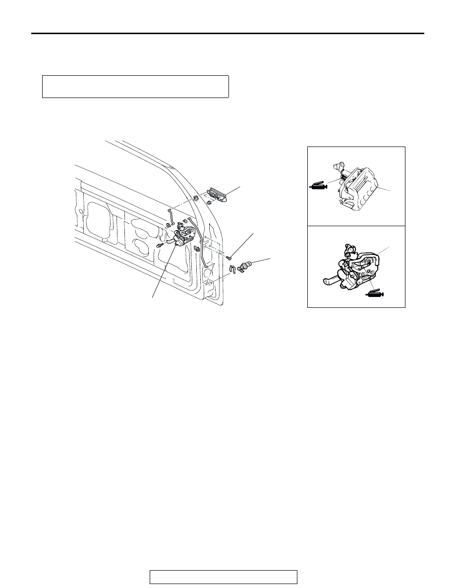
BACK DOOR HANDLE AND LATCH

REMOVAL AND INSTALLATION

M1423005800024

Post-installation Operation
• Outside Handle Play Inspection (Refer to 

P.42-49

.)

AX0129CA

18H0065

AX1146CA

ACX00569

1

1

2

5.9 – 1.0 N•m
52 – 9 in-lb

3

3

AB

BACK DOOR HANDLE AND LOCK KEY 
CYLINDER REMOVAL STEPS
• BACK DOOR TRIM AND 

WATERPROOF FILM 

• BACK DOOR GARNISH (REFER TO 

GROUP 51 

P.51-14

.)

1. BACK DOOR HANDLE
2. BACK DOOR LOCK KEY CYLINDER

BACK DOOR LATCH REMOVAL 
STEPS
• BACK DOOR TRIM AND 

WATERPROOF FILM 
(REFER TO 

P.42-52

.)

3. BACK DOOR LATCH ASSEMBLY

KEYLESS ENTRY SYSTEM

TSB Revision

BODY

42-54

INSPECTION

M1421007600398

BACK DOOR LOCK ACTUATOR CHECK

BACK DOOR LOCK KEY CYLINDER SWITCH 
CHECK 

KEYLESS ENTRY SYSTEM

GENERAL DESCRIPTION

M1428000100188

Some models are equipped with a keyless entry sys-
tem. The main features are:

• Antenna and receiver are incorporated in the 

ETACS-ECU.

• ID code can be registered by using the scan tool 

(MUT-II).

• Transmitter is a key holder type, which incorpo-

rates lock switch, unlock switch, and panic 
switch.

• The locking is answered back by two times' flash-

ing of the dome light, two times' flashing of the 
turn signal lights and one time sounding of the 
horn answerback.

• The unlocking is answered back by illuminating of 

the dome light for 15 seconds and one time flash-
ing of the turn signal lights.

KEYLESS ENTRY SYSTEM DIAGNOSIS

M1428000700027

The keyless entry system is controlled by the Smart 
Wiring System (SWS). For troubleshooting, refer to 
Group 54B, Diagnosis 

P.54Bb-2

.

LEVER 
POSITION

BATTERY CONNECTION

LEVER 
OPERATION

At the 
"LOCK" 
position

• Connect terminal 3 to 

the positive battery 
terminal

• Connect terminal 2 to 

the negative battery 
terminal

The lever moves 
from the "LOCK" 
position to the 
"UNLOCK" 
position.

At the 
"UNLOCK" 
position

• Connect terminal 3 to 

the negative battery 
terminal

• Connect terminal 2 to 

the positive battery 
terminal

The lever moves 
from the 
"UNLOCK" 
position to the 
"LOCK" position.

1 2 3

4 5 6

ACX00570

LOCK

UNLOCK

VIEW A

A

LEVER

AC

SWITCH 
POSITION

TESTER 
CONNECTION

SPECIFIED 
CONDITION

LOCK

− 2

Less than 2 ohms

NEUTRAL (OFF)

− 2, 1 − 3, 2 − 3

Open circuit

UNLOCK

− 3

Less than 2 ohms

ACX02411

1

2

3

KEYLESS ENTRY SYSTEM

TSB Revision

BODY

42-55

SPECIAL TOOLS

M1428000600020

ON-VEHICLE SERVICE

HOW TO REPLACE THE TRANSMITTER 
BATTERY

M1428000900173

CAUTION

Do not allow water or dust to enter the inside of the trans-
mitter when it is open. Also, do not touch the electronic 
device inside.
1. Remove the set screw to remove the battery from the 

transmitter.

2. Install a battery with its (+) side face-down.

Battery required for replacement: Coin type battery 
CR2032

3. Insert the claw first, taking with care not to displace the O-

ring, and assemble the transmitter.

4. Verify that the keyless entry system operates.

ENABLING/DISABLING THE ANSWERBACK 
FUNCTION

M1428003200010

If the keyless entry system locks or unlocks the doors, the 
dome light flashes or illuminates, the hazard warning light 
flashes (hazard answerback function) and the horn sounds 
(horn answerback function). The hazard and horn answerback 
functions can be enabled or disabled according to the following 
procedure:

ENABLING/DISABLING THE HAZARD 
ANSWERBACK FUNCTION

The hazard answerback function can be enabled or disabled by 
one of the two following procedures.

.

TOOL

TOOL NUMBER AND NAME SUPERSESSION

APPLICATION

MB991502 Scan tool (MUT-II) MB991496-OD

For checking of keyless entry 
system [Input signal check]

MB991529 Diagnostic trouble 
code check harness

Tool not necessary if 
scan tool (MUT-II) is 
available

For checking of keyless entry 
system [Input signal check]

B991502

MB991529

AC000123 AB

BATTERY

CLAW

SCREW

KEYLESS ENTRY SYSTEM

TSB Revision

BODY

42-56

<When the transmitter is used after connecting scan tool 
MB991502 to the data link connector or grounding data 
link connector terminal (1)>
Refer to GROUP 54B, SWS 

− On-vehicle Service 

P.54Ba-26

.

.

<When only the transmitter is used>
1. Remove the ignition key.
2. Push the "LOCK" switch while holding the "UNLOCK" switch 

pushed for four to ten seconds.

3. If the "LOCK" switch and "UNLOCK" switch are released in 

that order, the ETACS-ECU tone alarm will sound, indicating 
that the hazard answerback function can be enabled or 
disabled when the doors are locked.

• Enable the hazard answerback function when the 

doors are locked: The ETACS-ECU tone alarm will 
sound once.

• Disable the hazard answerback function when the 

doors are locked: The ETACS-ECU tone alarm will 
sound twice.

4. If the "UNLOCK" switch and "LOCK" switch are released in 

that order, the ETACS-ECU tone alarm will sound, indicating 
that the hazard answerback function can be enabled or 
disabled when the door are unlocked.

• Enable the hazard answerback function when the 

doors are unlocked: The ETACS-ECU tone alarm 
will sound once.

• Disable the hazard answerback function when the 

doors are unlocked: The ETACS-ECU tone alarm 
will sound twice.

ENABLING/DISABLING THE HORN 
ANSWERBACK FUNCTION

1. Remove the ignition key.
2. Push the "UNLOCK" switch while holding the "LOCK" switch 

pushed for four to ten seconds.

3. If the "LOCK" switch and "UNLOCK" switch are released at 

the same time, the ETACS-ECU tone alarm will sound, 
indicating that the horn answerback function can be enabled 
or disabled.

• Enable the horn answerback function: The ETACS-

ECU tone alarm will sound once.

• Disable the horn answerback function: The ETACS-

ECU tone alarm will sound twice.

SECRET CODE REGISTRATION METHOD

M1428001000195

Each individual secret code is registered inside the transmitter, 
and so it is necessary to resister these codes with the 
EEPROM inside the receiver in the following cases.

• When the transmitter or ETACS-ECU is replaced

• If more transmitters are to be used


Content   ..  12  13  14  15   ..