Mitsubishi Montero (1998+). Manual - part 144


  Index      Mitsubishi     Mitsubishi Montero - service repair manual 1998 year


Search            


Content   ..  142  143  144  145   ..


Mitsubishi Montero (1998+). Manual - part 144


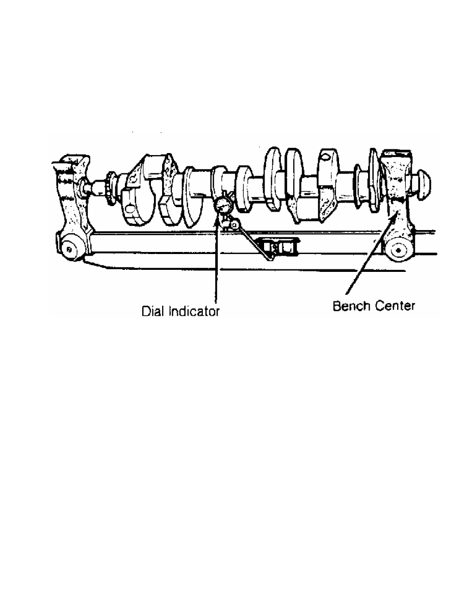
with tip resting on the main bearing journal area. See  Fig. 21.

Rotate crankshaft and note reading. Journal runout must not exceed

specification. Repeat procedure on all main bearing journals.

Crankshaft must be replaced if runout exceeds specification.

Fig. 21:  Measuring Crankshaft Main Bearing Journal Runout - Typical

This Graphic For General Information Only

         INSTALLATION

         Install upper main bearing in cylinder block. Ensure lock

tab is properly located in cylinder block. Install bearings in main

bearing caps. Ensure all oil passages are aligned. Install rear seal

(if removed).

         Ensure crankshaft journals are clean. Lubricate upper main

bearings with clean engine oil. Carefully install crankshaft. Check

each main bearing clearance using Plastigage method. See

MAIN & CONNECTING ROD BEARING CLEARANCE in this article.

         Once clearance is checked, lubricate lower main bearing and

journals. Install main bearing caps in original location. Install rear

seal in rear main bearing cap (if removed). Some rear main bearing

caps require sealant to be applied in corners to prevent oil leakage.

         Install and tighten all bolts except thrust bearing cap to

specification. Tighten thrust bearing cap bolts finger tight only.

Thrust bearing must be aligned. On most applications, crankshaft

must be moved rearward then forward. Procedure may vary with

manufacturer. Thrust bearing cap is then tighten to specification.

Ensure crankshaft rotates freely. Crankshaft end play should be

checked. See CRANKSHAFT END PLAY in this article.

         CRANKSHAFT END PLAY

         Dial Indicator Method

         Crankshaft end play can be checked using dial indicator.

Mount dial indicator on rear of cylinder block. Position dial

indicator tip against rear of crankshaft. Ensure tip is resting

against flat surface.

         Pry crankshaft rearward. Adjust dial indicator to zero.

Pry crankshaft forward and note reading. Crankshaft end play must be

within specification. If end play is not within specification, check

for faulty thrust bearing installation or worn crankshaft. Some

applications offer oversized thrust bearings.

         Feeler Gauge Method

         Crankshaft end play can be checked using feeler gauge. Pry

crankshaft rearward. Pry crankshaft forward. Using feeler gauge,

measure clearance between crankshaft and thrust bearing surface. See

Fig. 22.

Fig. 22:  Checking Crankshaft End Play - Typical

This Graphic For General Information Only

         Crankshaft end play must be within specification. If end

play is not within specification, check for faulty thrust bearing

installation or worn crankshaft. Some applications offer oversized

thrust bearings.

         CYLINDER BLOCK

         * PLEASE READ THIS FIRST *

NOTE:    Always refer to appropriate engine overhaul article in the

         ENGINES section for complete overhaul procedures and

         specifications for the vehicle being repaired.

         BLOCK CLEANING

         Only cast cylinder blocks should be hot tank cleaned.

Aluminum cylinder blocks should be cleaned using cold tank method.

Cylinder block is cleaned in order to remove carbon deposits, gasket

residue and water jacket scale. Remove oil galley plugs, freeze plugs

and cam bearings prior to block cleaning.

         BLOCK INSPECTION

         Visually inspect the block. Check suspected areas for cracks

using the Dye Penetrant inspection method. Block may be checked for

cracks using the Magnaflux method.

         Cracks are most commonly found at the bottom of the

cylinders, the main bearing saddles, near expansion plugs and between

the cylinders and water jackets. Inspect lifter bores for damage.

Inspect all head bolt holes for damaged threads. Threads should be

cleaned using tap to ensure proper head bolt torque. Consult machine

shop concerning possible welding and machining (if required).

         CYLINDER BORE INSPECTION

         Inspect the bore for scuffing or roughness. Cylinder bore

is dimensionally checked for out-of-round and taper using dial bore

gauge. For determining out-of-round, measure cylinder parallel and

perpendicular to the block centerline. Difference in the 2 readings

is the bore out-of-round. Cylinder bore must be checked at top, middle

and bottom of piston travel area.

         Bore taper is obtained by measuring bore at the top and

bottom. If wear has exceeded allowable limits, block must be honed

or bored to next available oversize piston dimension.

         CYLINDER HONING

         Cylinder must be properly honed to allow new piston rings to

properly seat. Cross-hatching at correct angle and depth is critical

to lubrication of cylinder walls and pistons.

         A flexible drive hone and power drill are commonly used.

Drive hone must be lubricated during operation. Mix equal parts of

kerosene and SAE 20w engine oil for lubrication.

         Apply lubrication to cylinder wall. Operate cylinder hone

from top to bottom of cylinder using even strokes to produce 45 degree

cross-hatch pattern on the cylinder wall. DO NOT allow cylinder hone

to extend below cylinder during operation.

         Recheck bore dimension after final honing. Wash cylinder

wall with hot soapy water to remove abrasive particles. Blow dry with

compressed air. Coat cleaned cylinder walls with lubricating oil.

         DECK WARPAGE

         Check deck for damage or warped head sealing surface. Place

a straightedge across gasket surface of the deck. Using feeler gauge,

measure clearance at center of straightedge. Measure across width and

length of cylinder block at several points.

         If warpage exceeds specifications, deck must be resurfaced.

If warpage exceeds manufacturer’s maximum tolerance for material

removal, replace block.

         DECK HEIGHT

         Distance from the crankshaft centerline to the block

deck is termed the deck height. Measure and record front and rear main

journals of crankshaft. To compute this distance, install crankshaft

and retain with center main bearing and cap only. Measure distance

from the crankshaft journal to the block deck, parallel to the

cylinder centerline.

         Add one half of the main bearing journal diameter to distance

from crankshaft journal to block deck. This dimension should be

checked at front and rear of cylinder block. Both readings should be

the same.

         If difference exceeds specifications, cylinder block must be

repaired or replaced. Deck height and warpage should be corrected at

the same time.

         MAIN BEARING BORE & ALIGNMENT

         For checking main bearing bore, remove all bearings from

cylinder block and main bearing caps. Install main bearing caps in

original location. Tighten bolts to specification. Using inside

micrometer, measure main bearing bore in 2 areas 90 degrees apart.

Determine bore size and out-of-round. If diameter is not within

specification, block must be align-bored.

         For checking alignment, place a straightedge along centerline

of main bearing saddles. Check for clearance between straightedge and

main bearing saddles. Block must be align-bored if clearance is

present.

         EXPANSION PLUG REMOVAL & INSTALLATION

         Removal

         Drill a hole in the center of expansion plug. Remove with

screwdriver or punch. Use care not to damage sealing surface.

         Installation

         Ensure sealing surface is free of burrs. Coat expansion plug

with sealer. Use a wooden dowel or pipe of slightly smaller diameter,

install expansion plug. Ensure expansion plug is evenly located.

         OIL GALLERY PLUG REMOVAL & INSTALLATION

         Removal

         Remove threaded oil gallery plugs using the appropriate

wrench. Soft, press-in plugs are removed by drilling into plug and

installing a sheet metal screw. Remove plug with slide hammer or

pliers.

         Installation

         Ensure threads or sealing surface is clean. Coat threaded oil

gallery plugs with sealer and install. Replacement soft press-in plugs

are driven in place with a hammer and drift.

         CAMSHAFT

         * PLEASE READ THIS FIRST *


Content   ..  142  143  144  145   ..