Mitsubishi Montero (1998+). Manual - part 143


  Index      Mitsubishi     Mitsubishi Montero - service repair manual 1998 year


Search            


Content   ..  141  142  143  144   ..


Mitsubishi Montero (1998+). Manual - part 143


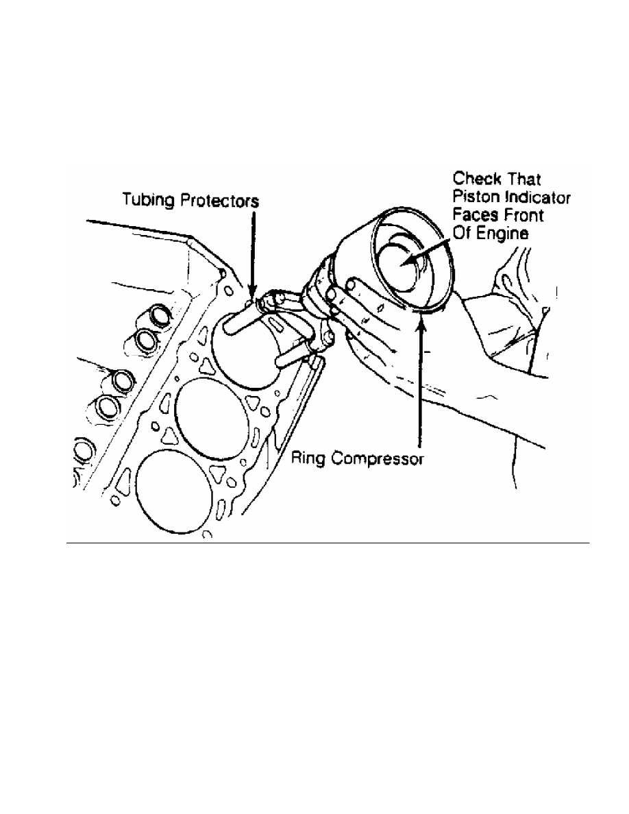
over connecting rod bolts. Install piston and connecting rod assembly.

Ensure piston notch, arrow or "FRONT" mark is toward front of engine.

See Fig. 17.

Fig. 17:  Installing Piston & Connecting Rod Assembly - Typical

This Graphic For General Information Only

         Carefully tap piston into cylinder until rod bearing is

seated on crankshaft journal. Remove protectors. Install rod cap and

bearing. Lightly tighten connecting rod bolts. Repeat procedure for

remaining cylinders. Check bearing clearance. See

MAIN & CONNECTING ROD BEARING CLEARANCE in this article.

         Once clearance is checked, lubricate journals and bearings.

Install bearing caps. Ensure marks are aligned on connecting rod and

cap. Tighten rod nuts or bolts to specification. Ensure rod moves

freely on crankshaft. Check connecting rod side clearance. See

CONNECTING ROD SIDE CLEARANCE in this article.

         CONNECTING ROD SIDE CLEARANCE

         Position connecting rod toward one side of crankshaft as far

as possible. Using feeler gauge, measure clearance between side of

connecting rod and crankshaft. See Fig. 18. Clearance must be within

specifications.

Fig. 18:  Measuring Connecting Rod Side Clearance - Typical

This Graphic For General Information Only

         Check for improper bearing installation, wrong bearing cap

or insufficient bearing clearance if side clearance is insufficient.

Connecting rod may require machining to obtain proper clearance.

Excessive clearance usually indicates excessive wear at crankshaft.

Crankshaft must be repaired or replaced.

         MAIN & CONNECTING ROD BEARING CLEARANCE

         Plastigage Method

         Plastigage method may be used to determine bearing clearance.

Plastigage can be used with an engine in service or during reassembly.

Plastigage material is oil soluble.

         Ensure journals and bearings are free of oil or solvent.

Oil or solvent will dissolve material and false reading will be

obtained. Install small piece of Plastigage along full length of

bearing journal. Install bearing cap in original location. Tighten

bolts to specification.

CAUTION: DO NOT rotate crankshaft while Plastigage is installed.

         Bearing clearance will not be obtained if crankshaft is

         rotated.

         Remove bearing cap. Compare Plastigage width with scale on

Plastigage container to determine bearing clearance. See  Fig. 19.

Rotate crankshaft 90 degrees. Repeat procedure. this is done to check

journal eccentricity. This procedure can be used to check oil

clearance on both connecting rod and main bearings.

Fig. 19:  Measuring Bearing Clearance - Typical

This Graphic For General Information Only

         Micrometer & Telescopic Gauge Method

         A micrometer is used to determine journal diameter, taper and

out-of-round dimensions of the crankshaft. See CLEANING & INSPECTION

under CRANKSHAFT & MAIN BEARINGS in this article.

         With crankshaft removed, install bearings and caps in

original location on cylinder block. Tighten bolts to specification.

On connecting rods, install bearings and caps on connecting rods.

Install proper connecting rod cap on corresponding rod. Ensure bearing

cap is installed in original location. Tighten bolts to specification.

         Using a telescopic gauge and micrometer or inside micrometer

measure inside diameter of connecting rod and main bearings bores.

Subtract each crankshaft journal diameter from the corresponding

inside bore diameter. This is the bearing clearance.

         CRANKSHAFT & MAIN BEARINGS

         * PLEASE READ THIS FIRST *

NOTE:    Always refer to appropriate engine overhaul article in the

         ENGINES section for complete overhaul procedures and

         specifications for the vehicle being repaired.

         REMOVAL

         Ensure all main bearing caps are marked for location on

cylinder block. Some main bearing caps have an arrow stamped on it

which must face front of engine. Remove main bearing cap bolts. Remove

main bearing caps. Carefully remove crankshaft. Use care not to bind

crankshaft in cylinder block during removal.

         CLEANING & INSPECTION

         Thoroughly clean crankshaft using solvent. Dry with

compressed air. Ensure all oil passages are clear and free of sludge,

rust, dirt, and metal chips.

         Inspect crankshaft for scoring and nicks. Inspect crankshaft

for cracks using Magnaflux procedure. Inspect rear seal area for

grooving or damage. Inspect bolt hole threads for damage. If pilot

bearing or bushing is used, check pilot bearing or bushing fit in

crankshaft. Inspect crankshaft gear for damaged or cracked teeth.

Replace gear if damaged. Check that oil passage plugs are tight (if

equipped).

         Using micrometer, measure all journals in 4 areas to

determine journal taper, out-of-round and undersize. See  Fig. 20.

Some crankshafts can be reground to the next largest undersize,

depending on the amount of wear or damage. Crankshafts with rolled

fillet cannot be reground and must be replaced.

Fig. 20:  Measuring Crankshaft Journal - Typical

This Graphic For General Information Only

         Crankshaft journal runout should be checked. Install

crankshaft in "V" blocks or bench center. Position dial indicator


Content   ..  141  142  143  144   ..