Mitsubishi Montero (1998+). Manual - part 86


  Index      Mitsubishi     Mitsubishi Montero - service repair manual 1998 year


Search            


Content   ..  84  85  86  87   ..


Mitsubishi Montero (1998+). Manual - part 86


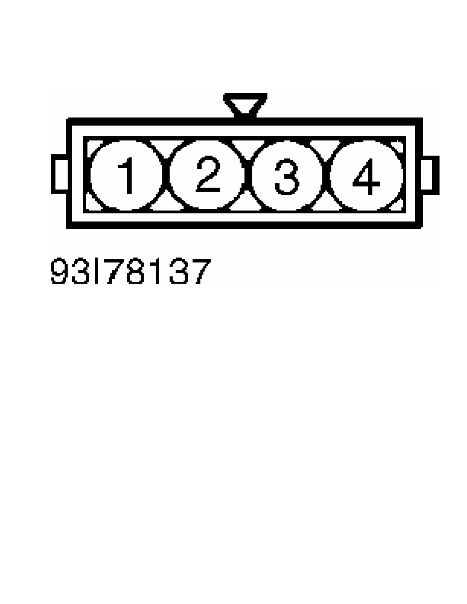
Fig. 9:  TP Sensor Connector Terminals (All Other Models)

Courtesy of Mitsubishi Motor Sales of America

DEFOGGER - REAR WINDOW 

1998 Mitsubishi Montero

         1998 ACCESSORIES & EQUIPMENT

         Mitsubishi - Rear Window Defoggers

         Diamante, Eclipse, Galant, Mirage, Montero, Montero Sport,

         3000GT

         DESCRIPTION & OPERATION

         Rear window defogger is a heating filament grid bonded to

inside of window. Rear window defogger is controlled by defogger

switch on instrument panel and a defogger relay.

         On Montero, a timer relay controls defogger operation for 9-

11 minutes, then turns defogger off. On Eclipse and Galant, defogger

timer circuit is integral with Electronic Timer Alarm Control System

(ETACS) ECU. Timer will operate defogger for 11 minutes then turn off,

even with defogger switch in ON position and indicator light

illuminated. On Diamante, timer will operate defogger for 20 minutes,

then turn off.

         COMPONENT LOCATIONS

COMPONENT LOCATIONS TABLE


Component                                           Location

A/C ECU

  Diamante  .........................  Behind Center Of Dash

Data Link Connector (DLC)  .......  Under Left Side Of Dash,

                                        Near Steering Column

Defogger Relay

  Montero Sport  .......................  Under Left Side Of

                                           Glove Compartment

  Except Montero Sport  ...................  On Relay Block,

                                    Behind Left Side Of Dash

Defogger Timer

  Diamante  .........................  Integral With A/C ECU

  Eclipse & Galant  ...............  Integral With ETACS-ECU

  Montero  ......................  Behind Left Side Of Dash,

                                              Behind Speaker

ETACS-ECU  .........................  Above Left Kick Panel,

                                           On Junction Block


         TROUBLE SHOOTING

         * PLEASE READ THIS FIRST *

NOTE:    For additional trouble shooting information on Eclipse and

         Galant, see SYMPTOM TESTS.

         DEFOGGER DOES NOT WORK

         Check for blown fuse, poor contact, defective defogger

switch, poor connection or open wire.

         DEFOGGER TIMER INOPERATIVE

         Check defogger switch or defogger timer. See  COMPONENT TESTS.

         INDICATOR LIGHT DOES NOT WORK

         Check for burned out bulb, open circuit or poor connection.

         INDICATOR LIGHT IS DIM

         Check rheostat or indicator bulb.

         SYMPTOM TESTS

         INPUT SIGNAL INSPECTION

NOTE:    The following information only applies to Eclipse and Galant.

NOTE:    Perform input signal inspection before proceeding with

         SYSTEM TESTS.

         Eclipse & Galant

         1) Input signal inspection can be performed using scan tool

or an analog voltmeter. To perform inspection using scan tool, go to

next step. To perform inspection using an analog voltmeter, go to step

3).

         2) Turn ignition off. Connect scan tool to Data Link

Connector (DLC). Turn ignition on and then off. If buzzer on scan tool

sounds when ignition was turned on, ECU input signal is normal. If

buzzer did not sound, go to SYSTEM TESTS.

         3) Turn ignition off. Connect DTC Check Harness (MB991529) to

DLC terminals No. 4 or 5 (ground) and terminal No. 9. See  Fig. 1.

Connect voltmeter leads to check harness leads. Turn ignition switch

on, then off. If voltmeter deflects once when ignition was turned on,

ECU input signal is normal. If voltmeter did not deflect, go to

SYSTEM TESTS.

Fig. 1:  Identifying Data Link Connector (DLC) Terminals

Courtesy of Mitsubishi Motor Sales of America

         SYSTEM TESTS

NOTE:    The following information only applies to Eclipse and Galant.

NOTE:    Perform INPUT SIGNAL INSPECTION before proceeding with

         SYSTEM TESTS. To identify circuit connector terminals, see

         WIRING DIAGRAMS.

         Communication With All Systems Not Possible (Eclipse &

         Galant)

         1) Check voltage between ground and Data Link Connector (DLC)

terminal No. 16 (Red/Black wire on Eclipse or Brown/Red wire on

Galant). See Fig. 1. If battery voltage is present, go to step 3). If

battery voltage is not present, go to next step.

         2) Check junction block connectors between DLC and power

supply. See WIRING DIAGRAMS. If connectors are okay, check circuit

between power supply and DLC. See WIRING DIAGRAMS. Repair as

necessary.

         3) Check continuity between ground and DLC terminals No. 4

and 5. If continuity is present, replace scan tool and retest. If

continuity is not present, check circuit between ground and DLC. See

WIRING DIAGRAMS. Repair as necessary.

         Communication With One-Shot Pulse Input Signal Only Is Not

         Possible (Eclipse & Galant)

         Check circuit between DLC and junction block No. 1. See

WIRING DIAGRAMS. Repair as necessary. If circuit is okay, check

harness connectors to ETACS-ECU, DLC and junction/joint connectors.

Repair as necessary. If connectors are okay, replace ECU.

         Defogger Does Not Operate With Defogger Switch ON (Eclipse &

         Galant)

         1) Check defogger switch input signal. See

INPUT SIGNAL INSPECTION. If switch input signal is okay, check

defogger circuit and relay. See DEFOGGER RELAY TEST under COMPONENT

TESTS. Repair or replace as necessary. If switch input signal is not

okay, go to next step.

         2) Check defogger switch. See DEFOGGER SWITCH TEST under

COMPONENT TESTS. Replace as necessary. If defogger switch is okay,

turn ignition on. Check voltage between ground and defogger switch

harness-side connector terminal No. 4 (Eclipse) or terminal No. 2

(Galant). See WIRING DIAGRAMS. If voltage reading is 5 volts (Eclipse)

or battery voltage (Galant), go to next step. If voltage reading is

not as specified, go to step 4).

         3) Check joint/junction connectors between switch, instrument

panel cluster and ETACS-ECU. See WIRING DIAGRAMS. Repair as necessary.

If connectors are okay, check circuit between defogger switch and

ground. Repair as necessary. If circuit is okay, replace ECU.

         4) Check harness connectors to ETACS-ECU and instrument panel

cluster. Repair as necessary. If connectors are okay, check circuit

between ECU and defogger switch. Repair as necessary.

         Defogger Relay Circuit System Check (Eclipse & Galant)

         1) Check defogger relay. See DEFOGGER RELAY TEST under

COMPONENT TESTS. Replace as necessary. If relay is okay, go to next

step.

         2) Check voltage between ground and relay harness-side

connector terminals No. 3 and 5. See WIRING DIAGRAMS. If battery

voltage is present, go to next step. If battery voltage is not

present, go to step 4).

         3) Check harness connectors to relay, ETACS-ECU, junction

block and rear wiring/liftgate. See WIRING DIAGRAMS. Repair as

necessary. If connectors are okay, check circuit between defogger

relay and rear defogger, defogger and ground, or defogger relay and

ECU. See WIRING DIAGRAMS. Repair as necessary. If circuits are okay,


Content   ..  84  85  86  87   ..