Mitsubishi Montero (1998+). Manual - part 40


  Index      Mitsubishi     Mitsubishi Montero - service repair manual 1998 year


Search            


Content   ..  38  39  40  41   ..


Mitsubishi Montero (1998+). Manual - part 40


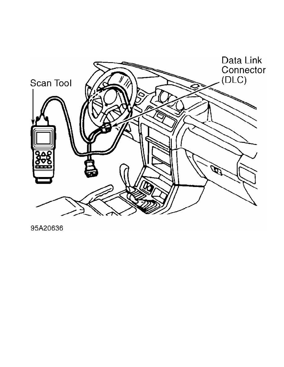
Fig. 5:  Retrieving Codes Using Scan Tool

Courtesy of Mitsubishi Motor Sales of America.

         Retrieving Codes Using Oil Temperature Warning Light

         1) Using jumper wire, ground DLC terminal No. 1. See  Fig. 6.

Note number of flashes from oil temperature warning light on

instrument panel. See Fig. 7. If normal system operation exists, oil

temperature warning light will blink 2 times per second. See  Fig. 8.

         2) If system is operating correctly and no DTC exists, turn

ignition off and remove jumper wire. If DTC exists, oil temperature

warning light will flash once every 2 seconds. The number of flashes

will equal first digit of DTC. After a pause of 2 seconds, second

digit will be displayed. Oil temperature warning light will flash once

every half second for second digit. See Fig. 8.

         3) If more than one DTC exists, next DTC will be displayed

after pause of 3 seconds. Smallest DTC number will be first. DTCs will

be repeated.

         4) Once DTC is obtained, determine probable cause and

symptom. See DIAGNOSTIC TROUBLE CODE IDENTIFICATION table. To trouble

shoot DTC, see DIAGNOSTIC TESTS. Turn ignition off and remove jumper

wire.

NOTE:    Once repairs have been performed, DTCs must be cleared from

         TCM memory. See CLEARING DIAGNOSTIC TROUBLE CODES (DTC).

         DIAGNOSTIC TROUBLE CODE IDENTIFICATION

DIAGNOSTIC TROUBLE CODE IDENTIFICATION


DTC                                                 ( 1) Probable Cause

11  ........................  Defective TP Sensor Or TP Sensor Circuit

15  .............................  Open Oil Temperature Sensor Circuit

16  ............................  Short Oil Temperature Sensor Circuit

21  ...................................  Short Ignition Signal Circuit

22  ....................................  Open Ignition Signal Circuit

23  ..........................  Open Signal Line (ECT) From ECM To TCM

24  .........................  Short Signal Line (ECT) From ECM To TCM

29  .............................  Short Neutral Safety Switch Circuit

30  ..............................  Open Neutral Safety Switch Circuit

31  .................................  Open No. 2 Speed Sensor Circuit

32  .................................  Open No. 1 Speed Sensor Circuit

41  .....................................  Open Solenoid No. 1 Circuit

42  ....................................  Short Solenoid No. 1 Circuit

43  .....................................  Open Solenoid No. 2 Circuit

44  ....................................  Short Solenoid No. 2 Circuit

47  ...................................  Open Lock-Up Solenoid Circuit

48  ..................................  Short Lock-up Solenoid Circuit

49  ..............  (2) Torque Converter Clutch Engagement Malfunction

50  ...........  (2) Torque Converter Clutch Disengagement Malfunction

51  .................................  1st Gear Ratio Signal Incorrect

52  .................................  2nd Gear Ratio Signal Incorrect

53  .................................  3rd Gear Ratio Signal Incorrect

54  .................................  4th Gear Ratio Signal Incorrect

(1) - Check listed fault code and component for probable cause. See

      appropriate fault code listing under DIAGNOSTIC TESTS. Check

      wiring and connections of specified component.

(2) - Scan tool is required for testing malfunctioning circuit.


Fig. 6:  Identifying Data Link Connector (DLC) Terminals

Courtesy of Mitsubishi Motor Sales of America.

Fig. 7:  Locating A/T Temperature Warning Light

Courtesy of Mitsubishi Motor Sales of America.

Fig. 8:  Identifying DTC Displays

Courtesy of Mitsubishi Motor Sales of America.

         CLEARING DIAGNOSTIC TROUBLE CODES (DTC)

         Once repairs have been performed, DTCs must be cleared from

TCM memory. DTCs may be cleared by disconnecting negative battery

cable for 10 seconds or more. Reconnect cable and ensure DTCs have

been cleared. Start engine and warm to normal operating temperature.

Run engine at idle for 10 minutes. DTCs may also be cleared using scan

tool. Refer to manufacturer’s instruction manual.

         DIAGNOSTIC TESTS

NOTE:    For terminal and wire color identification, see WIRING

         DIAGRAMS.

         DTC 11: THROTTLE POSITION (TP) SENSOR

         For diagnosis and testing information, see appropriate SELF-

DIAGNOSTICS article in ENGINE PERFORMANCE section. If TP sensor is

okay, check wiring harness and connectors between TP sensor and TCM.

Repair if necessary. If wiring harness and connectors are okay,

replace TCM.

         DTC 15 & 16: OPEN OR SHORT IN OIL TEMPERATURE SENSOR CIRCUIT

         1) Test oil temperature for proper operation. See OIL

TEMPERATURE SENSOR under COMPONENT TESTING. If oil temperature sensor

is okay, check wire harness, connectors and ground circuit for poor

connections or damage. Go to next step.

         2) If wire harness and connectors are okay, check DTCs again

and verify code No. 15 or No. 16 still exists. If either code still

exists, replace TCM.

         DTC 21 & 22: SHORT OR OPEN IN IGNITION SIGNAL CIRCUIT

         1) Using an external tachometer, verify vehicles’ tachometer

is operating accurately. If tachometer is incorrect, check ignition

coil and ignition power transistor and circuits for malfunction. See

appropriate SELF-DIAGNOSTICS article in ENGINE PERFORMANCE section.

         2) If tachometer is okay, check TCM wire harness connector

for poor connection. If wire harness is okay, recheck DTCs. If codes

reappear check wire harness between ignition power transistor and TCM.

If wire harness is okay, replace TCM.

         DTC 23 & 24: OPEN OR SHORT IN SIGNAL LINE (ECT) FROM ECM TO

         TCM

         Check wire harness, connectors and ground circuit for poor

connections or damage. Go to next step. If wire harness and connectors

are okay, check DTCs again and verify code No. 23 or No. 24 still

exists. If either code still exists, replace TCM.

         DTC 29 & 30: SHORT OR OPEN IN PARK/NEUTRAL POSITION (PNP)

         SWITCH CIRCUIT

         1) Check PNP switch for correct operation. See. If PNP switch

is okay, disconnect switch connector and measure voltage between

harness connector terminal No. 1 and ground.

         2) If battery voltage does not exist, check wire harness and

connectors. See WIRING DIAGRAMS. If battery voltage exists, check wire

harness and connectors between PNP switch and TCM. If wire harness is

okay, replace TCM.

         DTC 31: INPUT SPEED SENSOR


Content   ..  38  39  40  41   ..