Mitsubishi Montero (1998+). Manual - part 29


  Index      Mitsubishi     Mitsubishi Montero - service repair manual 1998 year


Search            


Content   ..  27  28  29  30   ..


Mitsubishi Montero (1998+). Manual - part 29


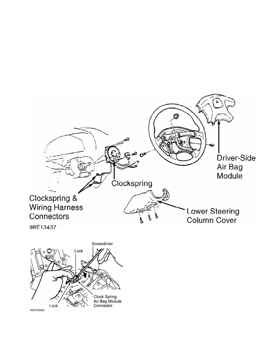
and screws. See Fig. 3. Lift air bag module for access to clockspring

connector at air bag module and disconnect clockspring connector. See

Fig. 4. Remove air bag module.

         3) Place air bag module on flat surface with trim cover

facing up. Remove steering wheel with Steering Wheel Puller

(MB990803). Remove lower column cover. Disconnect clockspring lower

connectors. Remove clockspring mounting screws. Remove clockspring.

See Fig. 3.

Fig. 3:  Removing Driver-Side Air Bag & Clockspring

Courtesy of Mitsubishi Motor Sales of America.

Fig. 4:  Disconnecting Clockspring Connector From Air Bag Module

Courtesy of Mitsubishi Motor Sales of America.

WARNING: If front wheels are not in straight-ahead position or

         clockspring mating marks are not aligned before installing

         clockspring, the steering wheel may not turn completely, or

         flat cable inside clockspring may be severed, disabling SRS

         system and possibly causing serious injury to driver.

         Installation

         1) Ensure front wheels are in straight-ahead position. Align

mating marks on clockspring. See CLOCKSPRING CENTERING under

ADJUSTMENTS. Install clockspring. To install remaining components,

reverse removal procedure. Before installing air bag module, ensure

horn switch wiring is positioned so that it will not be pinched.

         2) Tighten fasteners to spec. See  TORQUE SPECIFICATIONS.

Activate SRS. See DISABLING & ACTIVATING AIR BAG SYSTEM. Check AIR BAG

warning light for proper system function. SYSTEM OPERATION CHECK.

         PASSENGER-SIDE AIR BAG MODULE

         Removal & Installation

         1) Before proceeding, see SERVICE PRECAUTIONS. Deactivate

SRS. See DISABLING & ACTIVATING AIR BAG SYSTEM.

         2) Remove right-side foot shower duct and two stoppers on

either side. Remove and lower glove box. Disconnect air bag module

connector. Remove retaining bolts and passenger-side air bag module.

See Fig. 5.

         3) To install, reverse removal procedure. Tighten bolts to

specification. See TORQUE SPECIFICATIONS. Activate SRS. See procedures

under DISABLING & ACTIVATING AIR BAG SYSTEM. Check AIR BAG warning

light for proper system function. SYSTEM OPERATION CHECK.

Fig. 5:  Removing Passenger-Side Air Bag Module

Courtesy of Mitsubishi Motor Sales of America.

         SRS AIR BAG CONTROL UNIT (ECU)

CAUTION: SRS-ECU connector is a double-locking mechanism. DO NOT use

         excessive force when disconnecting connector.

         Removal & Installation

         1) Before proceeding, see SERVICE PRECAUTIONS. Deactivate

SRS. See DISABLING & ACTIVATING AIR BAG SYSTEM.

         2) Remove rear and front floor console assembly. Remove

switch panel and suspension control switch. Disconnect rear console

harness connector. Remove side panel A and rear console assembly.

         3) Remove shift lever. Disconnect front console harness

connector and remove front console assembly. Disconnect SRS-ECU

connector. Remove mounting bolts, bracket and SRS-ECU. See  Fig. 6.

         4) To install, reverse removal procedure. Tighten bolts to

specification. See TORQUE SPECIFICATIONS. Activate SRS. See procedures

under DISABLING & ACTIVATING AIR BAG SYSTEM. Check AIR BAG warning

light for proper system function. SYSTEM OPERATION CHECK.

Fig. 6:  Removing SRS Air Bag Control Unit (ECU)

Courtesy of Mitsubishi Motor Sales of America.

         FRONT IMPACT SENSORS

         Removal & Installation

         1) Before proceeding, see SERVICE PRECAUTIONS. Deactivate

SRS. See DISABLING & ACTIVATING AIR BAG SYSTEM.

         2) Remove components for access to front impact sensors as

necessary. See Fig. 7. Remove front impact sensor mounting bolts.

Slide Green section of connector to release lock. Push down on pawl.

Disconnect electrical connector. Remove front impact sensor.

         3) To install, reverse removal procedure. Position sensor

with arrow facing toward front of vehicle. Tighten bolts to

specification. See TORQUE SPECIFICATIONS. Activate SRS. See procedures

under DISABLING & ACTIVATING AIR BAG SYSTEM. Check AIR BAG warning

light for proper system function. SYSTEM OPERATION CHECK.

Fig. 7:  Locating Front Impact Sensors

Courtesy of Mitsubishi Motor Sales of America.

         ADJUSTMENTS


Content   ..  27  28  29  30   ..