Mitsubishi Montero (1991+). Manual - part 326


  Index      Mitsubishi     Mitsubishi Montero - service repair manual 1991 year


Search            


Content   ..  324  325  326  327   ..


Mitsubishi Montero (1991+). Manual - part 326


         Remove free wheeling hub. Measure caster with

camber/caster/kingpin gauge and turning radius gauge. See WHEEL

ALIGNMENT SPECIFICATIONS table. If caster is not within specification,

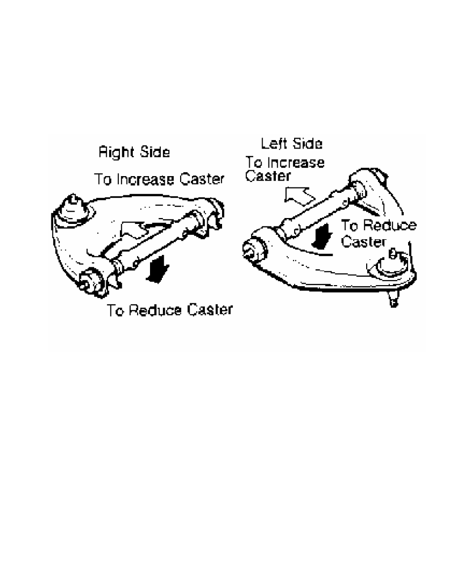
remove upper arm from crossmember. Adjust caster by turning upper arm

shaft. See Fig. 4.

Fig. 4:  Adjusting Caster (Montero)

Courtesy of Mitsubishi Motor Sales of America.

         Pickup & Ram-50

         1)  Check tire inflation. Place front wheel on turning radius

gauge, and level vehicle (unladed). On 2WD models, remove hub cap and

cotter pin. On 4WD models, remove free wheeling hub assembly.

         2) On all models, measure caster with camber/caster/kingpin

gauge attached. See WHEEL ALIGNMENT SPECIFICATIONS table. If caster is

not within specification, remove shock absorber mounting nut and lock

nut.

         3) Compress shock absorber and loosen upper arm mounting

bolts and nuts. Adjust caster by increasing or decreasing shims

between upper arm shaft and crossmember. See  Fig. 1.

CAUTION:  Difference in shim thickness between front and rear must be

          .16" (4 mm) or less. DO NOT use more than 3 shims at one

          location.

         All Other Models

         Check caster using a camber/caster/kingpin gauge and turning

radius gauge. See WHEEL ALIGNMENT SPECIFICATIONS table. If caster is

not to specification, replace damaged or bent parts.

         TOE-IN ADJUSTMENT

         Check toe-in. See WHEEL ALIGNMENT SPECIFICATIONS table. If

toe-in is not within specification, remove clips. Turn tie rods or

turnbuckles the same amount, but in opposite directions. Recheck toe-

in.

         TORQUE SPECIFICATIONS

TORQUE SPECIFICATIONS TABLE


Application                              Ft. Lbs. (N.m)

Shock Absorber-To-Crossmember Nut

  Montero, Pickup & Ram-50  ............  10-13 (14-18)

Shock Absorber-To-Lower Arm Bolt

  Montero  .............................  11-16 (15-22)

  Pickup & Ram-50  ...........................  10 (14)

Upper Arm Shaft To Crossmember

  Montero, Pickup & Ram-50  ...........  72-87 (98-118)

Wheel Lug Nut

  Colt Vista

   Aluminum Wheels  ...................  65-80 (88-108)

   Steel Wheels  .......................  50-57 (68-77)

  Eclipse, Pickup, Ram-50,

   Stealth & 3000GT  ................  87-101 (118-137)

  Montero  ............................  72-87 (98-118)

  All Others  .........................  65-80 (88-108)


         WHEEL ALIGNMENT SPECIFICATIONS

WHEEL ALIGNMENT SPECIFICATIONS TABLE (COLT, COLT 200, MIRAGE, SUMMIT)


Application                    Preferred                         Range

Camber (Degrees)

  Front  .......................  0  ....................  -1/2 to 1/2

  Rear  .....................  -11/16  ..............  -13/16 to -3/16

Caster (Degrees)  ...........  2 5/16  ...........  1 13/16 to 2 13/16

  Toe-In (In. (mm))

   Front  ....................  0 (0)  ........  -1/8 to 1/8 (-3 to 3)

   Rear  .....................  0 (0)  ......  -3/16 to 3/16 (-5 to 5)

  Toe-In (Degrees)

   Front  ......................  0  ....................  -1/4 to 1/4

   Rear  .......................  0  ....................  -3/8 to 3/8


WHEEL ALIGNMENT SPECIFICATIONS TABLE (COLT VISTA)


Application                    Preferred                         Range

Two Wheel Drive

  Camber (Degrees)

   Front  .....................  7/16  ..............  -1/16 to 15/16.

   Rear  .....................  -9/16  ..................  -1 1/8 to 0

  Caster (Degrees)  ..........  13/16  ................  5/16 to 15/16

  Toe-In (In. (mm))

   Front & Rear  .............  0 (0)  ........  -1/8 to 1/8 (-3 to 3)

  Toe-In (Degrees)

   Front & Rear  ...............  0  ....................  -1/4 to 1/4

  Toe-Out on Turns (Degrees)

   Inner  ....................  37 3/4  .......................  .....

   Outer  ...................  30 11/16  ......................  .....

Four Wheel Drive

  Camber (Degrees)

   Front  ....................  13/16  ................  5/16 to 15/16

   Rear  .......................  0  ....................  -1/2 to 1/2

  Caster (Degrees)  ..........  13/16  ................  5/16 to 15/16

  Toe-In (In. (mm))

   Front & Rear  .............  0 (0)  ........  -1/8 to 1/8 (-3 to 3)

  Toe-In (Degrees)

   Front & Rear  ...............  0  ....................  -1/4 to 1/4

  Toe-Out on Turns (Degrees)

   Inner  ...................  37 3/4  ........................  .....

   Outer  ..................  30 11/16  .......................  .....


WHEEL ALIGNMENT SPECIFICATIONS TABLE (ECLIPSE)


Application                    Preferred                         Range

1.8L Engine

  Camber (Degrees)

   Front  .....................  1/4  ...................  -1/4 to 3/4

   Rear  .....................  -3/4  ................  -1 1/4 to -1/4

  Caster (Degrees)  .........  2 5/16  ...........  1 13/16 to 2 13/16

  Toe-In (In. (mm))

   Front & Rear  .............  0 (0)  ........  -1/8 to 1/8 (-3 to 3)

  Toe-In (Degrees)

   Front & Rear  ...............  0  ....................  -1/4 to 1/4

2.0L Engine (2WD)

  Camber (Degrees)

   Front  ....................  1/16  .................  -7/16 to 9/16

   Rear  .....................  -3/4  ................  -1 1/4 to -1/4

  Caster (Degrees)  .........  2 3/8  ................  1 7/8 to 2 7/8

  Toe-In (In. (mm))

   Front & Rear  .............  0 (0)  ........  -1/8 to 1/8 (-3 to 3)

  Toe-In (Degrees)

   Front & Rear  ...............  0  ....................  -1/4 to 1/4

2.0L Engine (4WD)

  Camber (Degrees)

   Front  ....................  3/16  ................  -5/16 to 11/16

   Rear  ...................  -1 9/16  ...........  -2 1/16 to -1 1/16

  Caster (Degrees)  .........  2 5/16  ...........  1 13/16 to 2 13/16

  Toe-In (In. (mm))

   Front  ....................  0 (0)  ........  -1/8 to 1/8 (-3 to 3)

   Rear  ..................  9/64 (3.6)  ..  -1/32 to 1/4 (-.6 to 6.6)

  Toe-In (Degrees)

   Front  ......................  0  ....................  -1/4 to 1/4

   Rear  .....................  9/32  ...................  1/16 to 1/2


WHEEL ALIGNMENT SPECIFICATIONS TABLE (GALANT)


Application                    Preferred                         Range

Two Wheel Drive

  Camber (Degrees)

   Front  .....................  3/8  ...................  -1/8 to 7/8

   Rear  .....................  -3/4  ................  -1 1/4 to -1/4

  Caster (Degrees)  ............  2  .................  1 1/2 to 2 1/2

  Toe-In (In. (mm))

   Front & Rear  .............  0 (0)  ........  -1/8 to 1/8 (-3 to 3)

  Toe-In (Degrees)

   Front & Rear  ...............  0  ....................  -1/4 to 1/4

Four Wheel Drive

  Camber (Degrees)

   Front  .....................  1/2  ........................  0 to 1

   Rear  ......................  -1  .................  -1 1/2 to -1/2

  Caster (Degrees)  ........  1 15/16  .............  1 7/16 to 2 7/16

  Toe-In (In. (mm))

   Front  ....................  0 (0)  ........  -1/8 to 1/8 (-3 to 3)

   Rear  ....................  1/8 (3)  .........  0 to 1/4 (0 to 6.4)

  Toe-In (Degrees)

   Front  ......................  0  ....................  -1/4 to 1/4

   Rear  ......................  1/4  ......................  0 to 1/2


WHEEL ALIGNMENT SPECIFICATIONS TABLE (MONTERO)


Application                    Preferred                         Range

Camber (Front) (1)  .............  1  ..................  1/2 to 1 1/2

Caster (1)  ..................  2 15/16  .........  1 15/16 to 3 15/16

  Toe-In (Front) (2)  .......  7/32 (5.5)  ..  3/32 to 11/32 (2.5-8.5)

  Toe-In (Front) (1)  .........  7/16  ................  3/16 to 11/16

  Toe-Out on Turns (1)

   Inner  .....................  32 1/2  ......................  .....

   Outer  .......................  29  ........................  .....

(1) - Measurement in degrees.

(2) - Measurement in inches (mm).


WHEEL ALIGNMENT SPECIFICATIONS TABLE (RAM-50 & PICKUP)


Application                    Preferred                         Range

Two Wheel Drive

  Camber (Front) (1)  .........  11/16  ..............  3/16 to 1 3/16

  Caster (1)  .................  2 1/2  ..............  1 1/2 to 3 1/2

  Toe-In (Front) (2)  ......  7/32 (5.5)  ..  3/32 to 11/32 (2.5-8.5)

  Toe-In (Front) (1)  .........  7/16  ................  3/16 to 11/16

  Toe-Out on Turns (1)

   Inner  ......................  37  .........................  .....

   Outer  ....................  30 3/8  .......................  .....

Four Wheel Drive

  Camber (Front) (1)  ...........  1  ..................  1/2 to 1 1/2

  Caster (1)  ...................  2  ........................  1 to 3

  Toe-In (Front) (2)  .......  7/32 (5.5)  ..  3/32 to 11/32 (2.5-8.5)

  Toe-In (Front) (1)  .........  7/16  ................  3/16 to 11/16

  Toe-Out on Turns (1)

   Inner  ......................  30  .........................  .....

   Outer  ......................  27  .........................  .....

(1) - Measurement in degrees.

(2) - Measurement in inches (mm).


WHEEL ALIGNMENT SPECIFICATIONS TABLE (PRECIS)


Application                    Preferred                         Range

Camber (Degrees)

  Front  ........................  0  ...................  -1/2 to 1/2

  Rear  ......................  -11/16  .................  -1 to -3/16

Caster (Degrees)

  With P/S  ..................  1 11/16  ...........  1 3/16 to 2 3/16

  Without P/S  ..................  1  ..................  1/2 to 1 1/2

Toe-In (In. (mm))


Content   ..  324  325  326  327   ..