Mitsubishi Montero (1991+). Manual - part 317


  Index      Mitsubishi     Mitsubishi Montero - service repair manual 1991 year


Search            


Content   ..  315  316  317  318   ..


Mitsubishi Montero (1991+). Manual - part 317


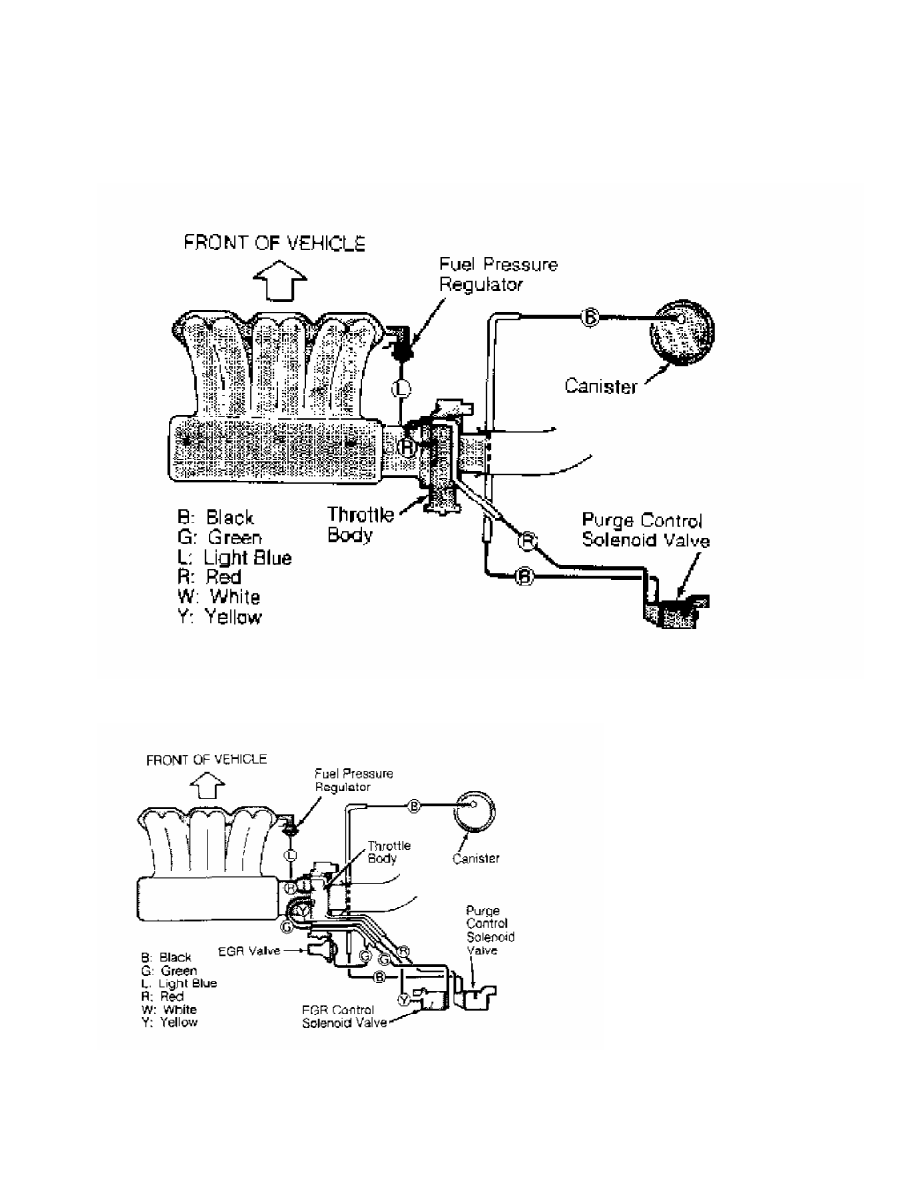
Fig. 21:  Vacuum Diagram (Stealth & 3000GT/Fed.)

Courtesy of Chrysler Motors.

Fig. 22:  Vacuum Diagram (Stealth & 3000GT/Calif.)

Courtesy of Chrysler Motors.

Fig. 23:  Vacuum Diagram (Stealth & 3000GT - Turbo/Calif. & Fed.)

Courtesy of Chrysler Motors.

WAVEFORMS - INJECTOR PATTERN TUTORIAL 


1991 Mitsubishi Montero

         GENERAL INFORMATION

         Waveforms - Injector Pattern Tutorial

         * PLEASE READ THIS FIRST *

NOTE:    This article is intended for general information purposes

         only. This information may not apply to all makes and models.

         PURPOSE OF THIS ARTICLE

         Learning how to interpret injector drive patterns from a Lab

Scope can be like learning ignition patterns all over again. This

article exists to ease you into becoming a skilled injector pattern

interpreter.

         You will learn:

      *  How a DVOM and noid light fall short of a lab scope.

      *  The two types of injector driver circuits, voltage controlled

         & current controlled.

      *  The two ways injector circuits can be wired, constant

         ground/switched power & constant power/switched ground.

      *  The two different pattern types you can use to diagnose with,

         voltage & current.

      *  All the valuable details injector patterns can reveal.

         SCOPE OF THIS ARTICLE

         This is NOT a manufacturer specific article. All different

types of systems are covered here, regardless of the specific

year/make/model/engine.

         The reason for such broad coverage is because there are only

a few basic ways to operate a solenoid-type injector. By understanding

the fundamental principles, you will understand all the major points

of injector patterns you encounter. Of course there are minor

differences in each specific system, but that is where a waveform

library helps out.

         If this is confusing, consider a secondary ignition pattern.

Even though there are many different implementations, each still has

a primary voltage turn-on, firing line, spark line, etc.

          If specific waveforms are available in On Demand for the

engine and vehicle you are working on, you will find them in the

Engine Performance section under the Engine Performance category.

         IS A LAB SCOPE NECESSARY?

         INTRODUCTION

         You probably have several tools at your disposal to diagnose

injector circuits. But you might have questioned "Is a lab scope

necessary to do a thorough job, or will a set of noid lights and a

multifunction DVOM do just as well?"

         In the following text, we are going to look at what noid

lights and DVOMs do best, do not do very well, and when they can

mislead you. As you might suspect, the lab scope, with its ability to

look inside an active circuit, comes to the rescue by answering for

the deficiencies of these other tools.

         OVERVIEW OF NOID LIGHT

         The noid light is an excellent "quick and dirty" tool. It can

usually be hooked to a fuel injector harness fast and the flashing

light is easy to understand. It is a dependable way to identify a no-

pulse situation.

         However, a noid light can be very deceptive in two cases:

      *  If the wrong one is used for the circuit being tested.

         Beware: Just because a connector on a noid light fits the

         harness does not mean it is the right one.

      *  If an injector driver is weak or a minor voltage drop is

         present.

         Use the Right Noid Light

         In the following text we will look at what can happen if the

wrong noid light is used, why there are different types of noid lights

(besides differences with connectors), how to identify the types of

noid lights, and how to know the right type to use.

         First, let’s discuss what can happen if the incorrect type of

noid light is used. You might see:

      *  A dimly flashing light when it should be normal.

      *  A normal flashing light when it should be dim.

         A noid light will flash dim if used on a lower voltage

circuit than it was designed for. A normally operating circuit would

appear underpowered, which could be misinterpreted as the cause of a

fuel starvation problem.

         Here are the two circuit types that could cause this problem:

      *  Circuits with external injector resistors. Used predominately

         on some Asian & European systems, they are used to reduce the

         available voltage to an injector in order to limit the

         current flow. This lower voltage can cause a dim flash on a

         noid light designed for full voltage.

      *  Circuits with current controlled injector drivers (e.g. "Peak

         and Hold"). Basically, this type of driver allows a quick

         burst of voltage/current to flow and then throttles it back

         significantly for the remainder of the pulse width duration.

         If a noid light was designed for the other type of driver

         (voltage controlled, e.g. "Saturated"), it will appear dim

         because it is expecting full voltage/current to flow for the

         entire duration of the pulse width.

         Let’s move to the other situation where a noid light flashes

normally when it should be dim. This could occur if a more sensitive

noid light is used on a higher voltage/amperage circuit that was

weakened enough to cause problems (but not outright broken). A circuit

with an actual problem would thus appear normal.

         Let’s look at why. A noid light does not come close to

consuming as much amperage as an injector solenoid. If there is a

partial driver failure or a minor voltage drop in the injector

circuit, there can be adequate amperage to fully operate the noid

light BUT NOT ENOUGH TO OPERATE THE INJECTOR.

         If this is not clear, picture a battery with a lot of

corrosion on the terminals. Say there is enough corrosion that the

starter motor will not operate; it only clicks. Now imagine turning on

the headlights (with the ignition in the RUN position). You find they

light normally and are fully bright. This is the same idea as noid

light: There is a problem, but enough amp flow exists to operate the

headlights ("noid light"), but not the starter motor ("injector").

         How do you identify and avoid all these situations? By using

the correct type of noid light. This requires that you understanding


Content   ..  315  316  317  318   ..