Mitsubishi Montero (1991+). Manual - part 6


  Index      Mitsubishi     Mitsubishi Montero - service repair manual 1991 year


Search            


Content   ..  4  5  6  7   ..


Mitsubishi Montero (1991+). Manual - part 6


tensioner center bolt. Using Tensioner Pulley Socket (MD998767) and

torque wrench, apply 84 INCH lbs. (9.5 N.m). See  Fig. 17. Retighten

center bolt to specification. See TORQUE SPECIFICATIONS (3000GT) table

at end of article. Ensure tensioner pulley does not rotate while

tightening center bolt.

         10) Ensure wire installed in automatic tensioner can be

easily removed and installed. Rotate crankshaft 2 revolutions

clockwise. Wait 5 minutes. Ensure wire can still be removed and

installed easily or automatic tensioner rod projects from tensioner

body .150-.177" (3.8-4.5 mm).

         11) If rod projection is not to specification, repeat steps

9) and 10). To complete installation, reverse removal procedure.

Install proper length bolts in timing belt covers. Install bolts into

engine support bracket in reverse order of removal sequence. See

Fig. 10. Tighten bolts to specification. See TORQUE SPECIFICATIONS

(3000GT) table.

NOTE:    Engine support bracket reamer bolt must be tightened slowly

         while spraying lubricant on bolt.

         CAMSHAFT & ROCKER ARMS

         Removal (SOHC)

         1) Remove PCV valve and breather hoses. Remove timing belt,

camshaft sprocket and rear timing belt cover. See TIMING BELT under

REMOVAL & INSTALLATION. Remove rocker covers and gaskets. Remove

circular packing from rear of camshafts.

         2) Remove camshaft oil seal from front of cylinder head or

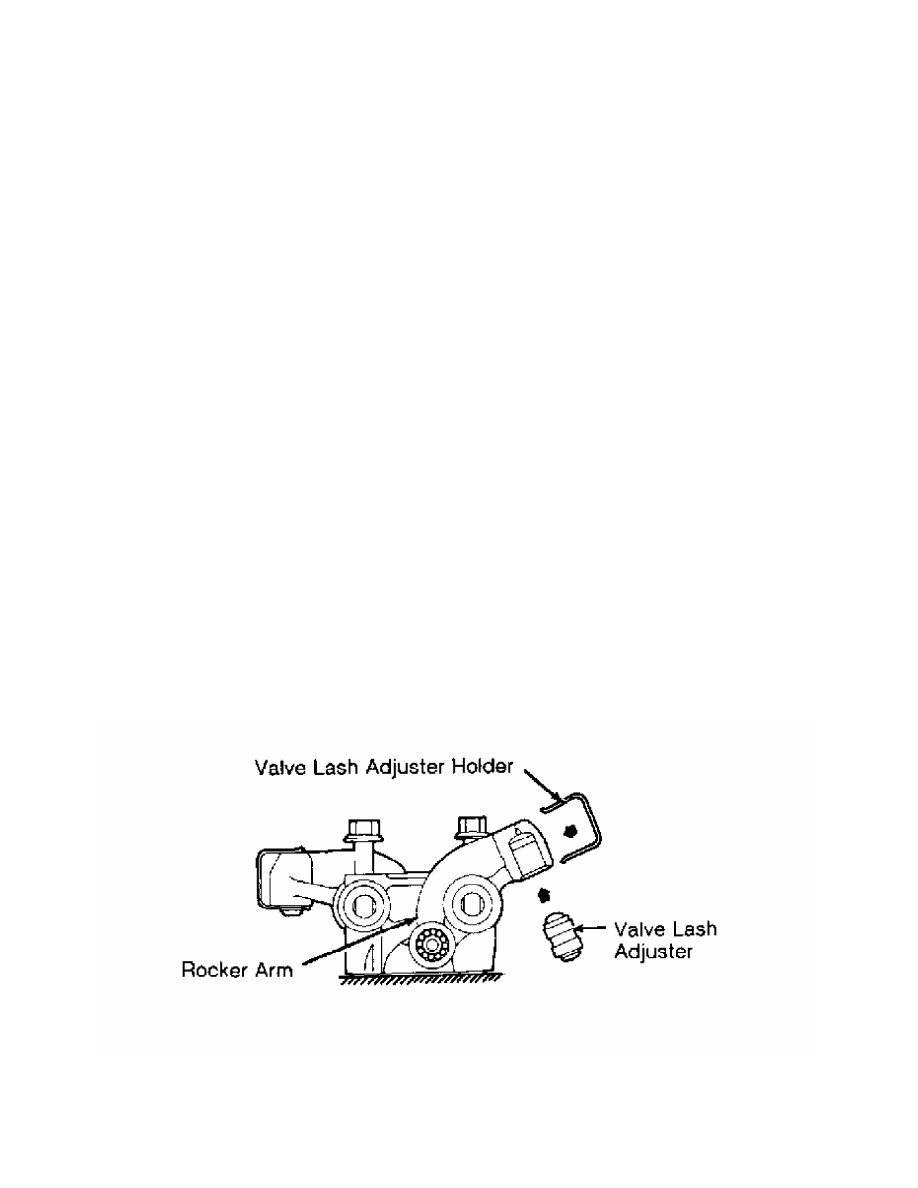
distributor adapter. Remove distributor adapter and "O" ring. Install

Valve Lash Adjuster Holder (MD998443) on rocker arm. See  Fig. 18. Note

arrow marks on bearing caps and cylinder head. See  Fig. 19.

         3) Bearing cap location number is stamped on front side of

bearing cap. Remove bearing cap bolts. Keep components in order for

reassembly reference. Remove rocker arm assembly. Remove camshaft from

cylinder head.

Fig. 18:  Installing Valve Lash Adjuster Holder (SOHC)

Courtesy of Mitsubishi Motor Sales of America, Inc.

Fig. 19:  Identifying Bearing Cap & Sealant Locations (SOHC)

Courtesy of Mitsubishi Motor Sales of America, Inc.

         Inspection (SOHC)

         1) Remove bearing caps, rocker arms and springs from shafts.

Mark component location for reassembly reference. Inspect rocker arm

and shaft for damaged roller and flaking. Measure rocker arm I.D. and

rocker arm shaft O.D. Determine oil clearance. Check spring free

length. Replace components if not within specification. See ROCKER ARM

& SHAFT SPECIFICATIONS (SOHC) table.

         2) Inspect camshaft and distributor gear for damage. Measure

camshaft end play, journal diameter and lobe height. Replace camshaft

if it is not within specification. See CAMSHAFT (SOHC) table under

ENGINE SPECIFICATIONS at end of article.

         3) Coat components with oil. Reassemble rocker arms, springs

and bearing caps. Install bearing caps with identification number

toward camshaft sprocket. Ensure oil holes and notch of shafts are

properly positioned. See Fig. 19.

ROCKER ARM & SHAFT SPECIFICATIONS TABLE (SOHC)


Application                                         In. (mm)

Oil Clearance  .................  (1).0004-.0016 (.010-.041)

Rocker Arm I.D.  ............................  .7444 (18.91)

Rocker Arm Shaft O.D.  ......................  .7440 (18.90)

Spring Free Length  .........................  2.173 (55.19)

(1) - Maximum clearance is .0039" (.099 mm).


Fig. 20:  Installing Rocker Arm Shafts (SOHC)

Courtesy of Mitsubishi Motor Sales of America, Inc.

         Installation

         1) Coat camshaft with oil, and install in cylinder head.

Install valve lash adjusters and valve lash adjuster holders (if

removed). See Fig. 18.

         2) Apply 3M Sealant (4171) to designated areas of cylinder

head. See Fig. 19. Use care so sealant does not get on camshaft or

camshaft bearing journals. Install rocker arm assembly. Ensure arrow

on bearing cap faces same direction as arrow on cylinder head. See

Fig. 19. Tighten bearing cap bolts to specification. See appropriate

TORQUE SPECIFICATIONS table at end of article. Remove valve lash

adjuster holders.

         3) Coat camshaft oil seal area with oil. Using Seal Installer

(MD998713), install camshaft oil seal. Using Circular Packing

Installer (MD998306), install circular packing to press-in depth of .

02" (.5 mm).

         4) Apply Three Bond (1212D) sealant to rocker cover sealing

surfaces before installation. See Fig. 6. Coat new "O" ring with oil,

and install on distributor adapter (if removed).

         5) Coat camshaft area with oil before installing distributor

adapter. To complete installation, reverse removal procedure. Tighten

bolts to specification. See appropriate TORQUE SPECIFICATIONS table.

         Removal (DOHC)

         1) Remove UPPER INTAKE MANIFOLD and LOWER INTAKE MANIFOLD as

necessary. See UPPER INTAKE MANIFOLD and LOWER INTAKE MANIFOLD under

REMOVAL & INSTALLATION. Remove timing belt, camshaft sprockets and

rear timing belt covers. See TIMING BELT under REMOVAL & INSTALLATION.

         2) Remove center cover and spark plug wires. Remove PCV and

breather hoses. Remove rocker covers and gaskets. Remove crank angle

sensor adapter. Remove front and rear camshaft bearing caps along with

seals and circular packings.

         3) Remove remaining camshaft bearing caps in sequence: No. 2,

No. 4 and No. 3. Remove camshaft, rocker arms and lash adjusters. Mark

component location for reassembly reference.

         Inspection (DOHC)

         Inspect rocker arm for damaged roller and flaking. Inspect

camshaft for damage. Measure camshaft end play, journal diameter and

lobe height. Replace camshaft if it is not within specification. See

CAMSHAFT (DOHC) table in ENGINE SPECIFICATIONS at end of article.

         Installation (DOHC)

         1) Coat components with oil. Install lash adjusters and

rocker arms. Bring No. 1 cylinder to TDC. Ensure intake and exhaust

camshafts are installed correctly. Intake camshaft is marked with a

"V" and exhaust camshaft is marked with a "C" on hexagon section.

Position camshaft dowels as shown. See Fig. 21.

NOTE:    If cylinder head is off vehicle, support cylinder head at

         least .39" (10 mm) above work surface to prevent valve

         damage while installing camshaft bearing caps.

Fig. 21:  Installing Camshafts & Bearing Caps (DOHC)

Courtesy of Mitsubishi Motor Sales of America, Inc.

         2) Install camshaft bearing caps in sequence: No. 3, No. 4


Content   ..  4  5  6  7   ..