Mitsubishi Montero (1991+). Manual - part 4


  Index      Mitsubishi     Mitsubishi Montero - service repair manual 1991 year


Search            


Content   ..  1  2  3  4  5  ..


Mitsubishi Montero (1991+). Manual - part 4


revolutions clockwise. DO NOT rotate counterclockwise. Realign all

timing marks. Tighten belt tensioner bolts to specification. Using

belt tension gauge, measure belt tension halfway between crankshaft

sprocket and camshaft sprocket on side opposite belt tensioner.

         7) Belt tension should be 57.3-83.8 lbs. (26-38 kg). To

install remaining components, reverse removal procedure. Install

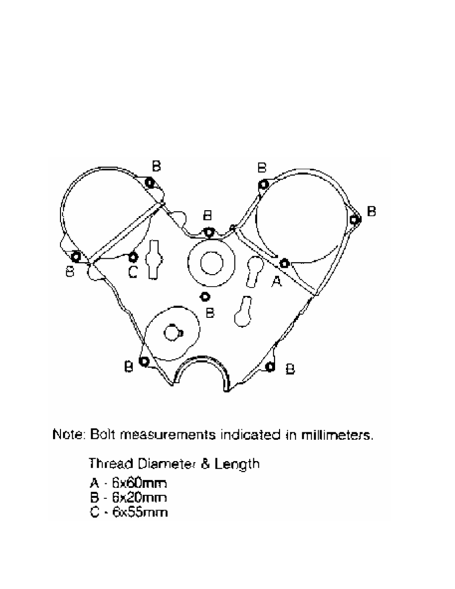
proper length bolts in timing belt covers. See  Fig. 9. Tighten bolts

to specification. See TORQUE SPECIFICATIONS (MONTERO & PICKUP) table.

Fig. 9:  Identifying Timing Belt Cover Bolt Lengths (MONTERO & PICKUP)

Courtesy of Mitsubishi Motor Sales of America, Inc.

Fig. 10:  Engine Support Bracket Bolt Removal Sequence (3000GT)

Courtesy of Mitsubishi Motor Sales of America, Inc.

NOTE:    Apply spray lubricant on reamer bolt during removal as bolt

         is sometimes seized in engine support bracket.

         Removal (3000GT)

         1) Remove lower splash shields. Remove cruise control

actuator (if equipped). Remove all drive belts. Disconnect electrical

connector at power steering pump. Remove A/C tensioner pulley and

mounting bracket.

         2) Remove power steering pump with hoses connected, and wire

aside. Support engine. Remove front engine mount through bolt and

front engine mount. Remove timing belt No. 1 upper outer cover and

gaskets. See Fig. 7.

         3) Remove engine support bracket bolts in proper sequence.

See Fig. 10. Remove engine support bracket. Remove cover cap and

timing belt No. 2 upper outer cover and gaskets. Using Holder

(MB990767) and Adapter Bolts (MD998719), remove crankshaft pulley.

         4) Remove lower outer cover, gaskets and flange. See  Fig. 7.

Rotate crankshaft and align all timing marks. See  Fig. 8. Loosen belt

tensioner bolt, and rotate belt tensioner counterclockwise to release

belt tension.

         5) If reusing timing belt, place arrow on belt to indicate

direction of belt rotation. Remove timing belt and belt tensioner.

         6) If camshaft sprocket requires removal, install Holder

(MB990767) with Adapter Bolts (MD998719) on camshaft sprocket. Remove

camshaft sprocket bolt and camshaft sprocket. Remove rear timing belt

cover (if required).

         Inspection (3000GT)

         Inspect timing belt for wear on edges of drive teeth. Inspect

belt for oil contamination. Replace belt if damaged or contaminated.

Inspect belt tensioner for smooth rotation. Replace if defective.

         Installation

         1) Install rear timing belt cover. Tighten bolts to

specification. See TORQUE SPECIFICATIONS (3000GT) table at end of

article. Install camshaft sprockets (if removed). Using holder, hold

camshaft and tighten camshaft sprocket bolt to specification.

         2) Install belt tensioner and spring. Ensure spring is

secured on pin of water pump and engaged in hole of belt tensioner

with hook of spring pointing from cylinder block.

         3) Rotate belt tensioner counterclockwise as much as

possible, and temporarily tighten bolt. Align all timing marks with

No. 1 cylinder at TDC of compression stroke. See  Fig. 8.

         4) Install timing belt on crankshaft sprocket, rear cylinder

bank camshaft sprocket, water pump pulley, front cylinder bank

camshaft sprocket and timing belt tensioner. Ensure belt is installed

in original direction of rotation and all timing marks are aligned.

Install flange on crankshaft. Loosen belt tensioner bolts slightly,

and allow tensioner to apply belt tension.

         5) Using Crankshaft Socket (MD998716), rotate crankshaft 2

revolutions clockwise. DO NOT rotate counterclockwise. Realign all

timing marks. Tighten belt tensioner bolts to specification. See

TORQUE SPECIFICATIONS (3000GT) table. Using belt tension gauge,

measure belt tension halfway between crankshaft sprocket and camshaft

sprocket on side opposite belt tensioner.

         6) Belt tension should be 46.3-63.3 lbs. (21-29 kg). To

install remaining components, reverse removal procedure. Install

proper length bolts in timing belt covers and engine support bracket.

See Figs. 9 and 10. Tighten bolts to specification. See TORQUE

SPECIFICATIONS (3000GT) table.

NOTE:    Engine support bracket reamer bolt must be tightened slowly

         while spraying lubricant on bolt.

Fig. 11:  Identifying Timing Belt Cover Bolt Length (SOHC)

Courtesy of Mitsubishi Motor Sales of America, Inc.

         Removal (DOHC)

         1) Remove lower splash shields. Remove cruise control

actuator (if equipped). Remove all drive belts. Remove alternator.

Remove drive belt tensioner assembly.

         2) Using Holder (MB990767) and Adapter Bolts (MD998754),

remove crankshaft pulley. See Fig. 12. Disconnect brake fluid level

sensor. Remove upper timing belt covers. Support engine. Remove front

engine mount through bolt and front engine mount.

NOTE:    Apply spray lubricant on reamer bolt during removal as bolt

         is sometimes seized in engine support bracket.

Fig. 12:  Exploded View of Timing Belt Components (DOHC)

Courtesy of Mitsubishi Motor Sales of America, Inc.

         3) Remove drive belt idler pulley. Remove engine support

bracket bolts in proper sequence. See Fig. 10. Remove engine support


Content   ..  1  2  3  4  5  ..