Mitsubishi Galant (2004+). Manual - part 957
 

  Index      Mitsubishi     Mitsubishi Galant - service repair manual 2004 year


Search            


Content   ..  955  956  957  958   ..


Mitsubishi Galant (2004+). Manual - part 957


MULTIPORT FUEL INJECTION (MFI) DIAGNOSIS

TSB Revision

MULTIPORT FUEL INJECTION (MFI) <2.4L ENGINE>

13A-645

FUEL TANK 
DIFFERENTIAL 
PRESSURE 
SENSOR

POWERTRAIN 
CONTROL 
MODULE

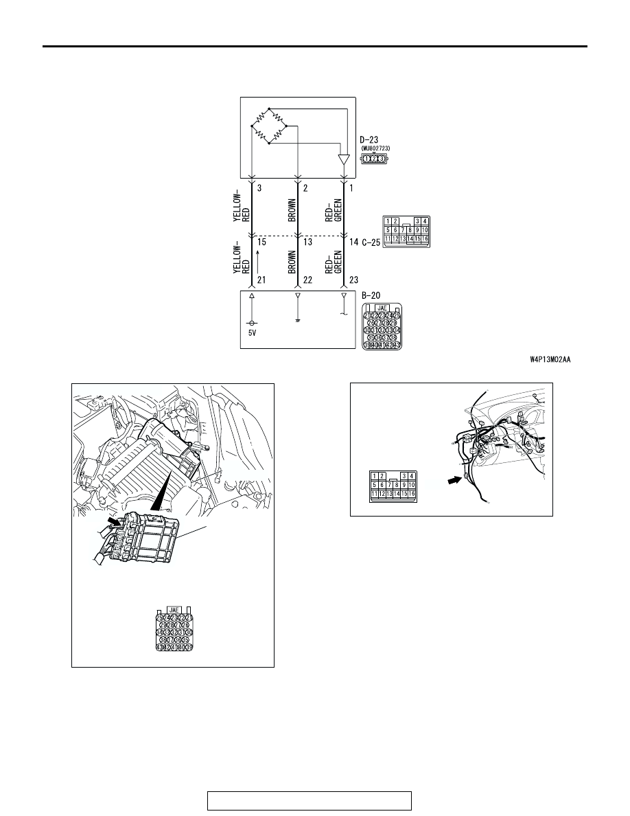
Fuel Tank Differential Pressure Sensor Circuit

AC306128

AC306248

B-20 HARNESS

CONNECTOR:

COMPONENT SIDE

AB

B-20

CONNECTOR: B-20

PCM

AIR
CLEANER

AC305231

CONNECTOR: C-25

AM

C-25

MULTIPORT FUEL INJECTION (MFI) DIAGNOSIS

TSB Revision

MULTIPORT FUEL INJECTION (MFI) <2.4L ENGINE>

13A-646

.

CIRCUIT OPERATION

• The PCM (terminal 21) supplies a 5-volt refer-

ence signal to the fuel tank differential pressure 
sensor (terminal 3). The fuel tank differential 
pressure sensor (terminal 2) is grounded through 
the PCM (terminal 22).

• The fuel tank differential pressure sensor (termi-

nal 1) returns a voltage signal to the PCM (termi-
nal 23) that is proportional to the pressure in the 
fuel tank.

.

TECHNICAL DESCRIPTION

• The PCM monitors the fuel tank differential pres-

sure sensor signal voltage.

• The PCM determines whether the fuel tank differ-

ential pressure sensor signal voltage is within 
normal operating parameters.

.

DESCRIPTIONS OF MONITOR METHODS

• Detect malfunction if change of fuel tank differen-

tial pressure sensor output voltage during idling 
stays large during specified go/stop operations.

.

MONITOR EXECUTION

• Continuous.

.

MONITOR EXECUTION CONDITIONS (Other 
Monitor and Sensor)

Other Monitor (There is no temporary DTC stored 

in memory for the item monitored below)

• Evaporative emission purge solenoid monitor

• Evaporative emission ventilation solenoid monitor

 Sensor (The sensors below are determined to be 

normal)

• Mass airflow sensor

• Barometric pressure sensor

• Intake air temperature sensor

• Engine coolant temperature sensor

.

AC305266

CONNECTOR: D-23

AB

D-23 (B)

MULTIPORT FUEL INJECTION (MFI) DIAGNOSIS

TSB Revision

MULTIPORT FUEL INJECTION (MFI) <2.4L ENGINE>

13A-647

LOGIC FLOW CHARTS (Monitor Sequence)

.

DTC SET CONDITIONS

Check Conditions

• Throttle valve is closed.

• Vehicle speed is 1.5 km/h (0.93 mph) or less.

Judgment Criteria

• If the voltage signal from the fuel tank differential 

pressure sensor changes by 0.2 volt or more, 
DTC P0451 will set. The code may also set if a 
sudden pressure fluctuation occurs twenty times 
while the engine is idling, and then eight consec-
utive times during normal driving.

START


YES

NO


NO


OFF-IDLING CONDITION


IDLING CONDITION?


F1 = 0


END


NO

NO

YES


YES


MALFUNCTION


F1 > 20


SPECIFIED TIMES

MONITORED


FTPS OUTPUT


VOLTAGE      > 0.2V


FLUCTUATION


NO 

YES


YES

F1 = F1 + 1


GOOD


YES


NO


OFF-IDLING CONDITION

AC306647

RATIONALITY - NOISE

MULTIPORT FUEL INJECTION (MFI) DIAGNOSIS

TSB Revision

MULTIPORT FUEL INJECTION (MFI) <2.4L ENGINE>

13A-648

NOTE: If the number of sudden pressure fluctua-
tions does not reach twenty during any one 
period of engine idling, or if the ignition switch is 
turned OFF, the counter will reset to zero.
NOTE: The conditions for deviating from idling 
operation are as follows:

.

Engine speed is greater than 2,500 r/min.

Vehicle speed is 15 km/h (9.3 mph) or 
greater.

Volumetric efficiency is 55 percent or greater.

.

OBD-ll DRIVE CYCLE PATTERN
Refer to Diagnostic Function 

− OBD-ll Drive Cycle − 

Procedure 1 

− Evaporative Emission System Leak 

Monitor 

P.13A-5

.

.

TROUBLESHOOTING HINTS (The most likely 
causes for this code to be set are:)

• Malfunction of the fuel tank differential pressure 

sensor.

• A damaged harness in the fuel tank differential 

pressure sensor circuit.

• Malfunction of the PCM.

.

OVERVIEW OF TROUBLESHOOTING

•  DTC P0451 can be set by a faulty fuel tank differ-

ential pressure sensor or related circuit, or PCM 
failure.

• To check for system blockage, do a performance 

test which uses a mechanical vacuum gauge and 
scan tool MB991958 set on the fuel tank differen-
tial pressure sensor (TANK PRS SNSR 73). The 
mechanical gauge reading is used to verify scan 
tool MB991958 reading. A comparison of the 
mechanical gauge with the reading on scan tool 
MB991958 will locate a problem in the system.

DIAGNOSIS

Required Special Tools:

• MB991958: Scan Tool (MUT-III Sub Assembly)

• MB991824: V.C.I.

• MB991827: MUT-III USB Cable

• MB991910: MUT-III Main Harness A

• MB991658: Test Harness Set

• MB991923: Power Plant ECU Check Harness


Content   ..  955  956  957  958   ..