Mitsubishi Galant (2004+). Manual - part 944
MULTIPORT FUEL INJECTION (MFI) DIAGNOSIS
TSB Revision
MULTIPORT FUEL INJECTION (MFI) <2.4L ENGINE>
13A-593
DTC SET CONDITIONS
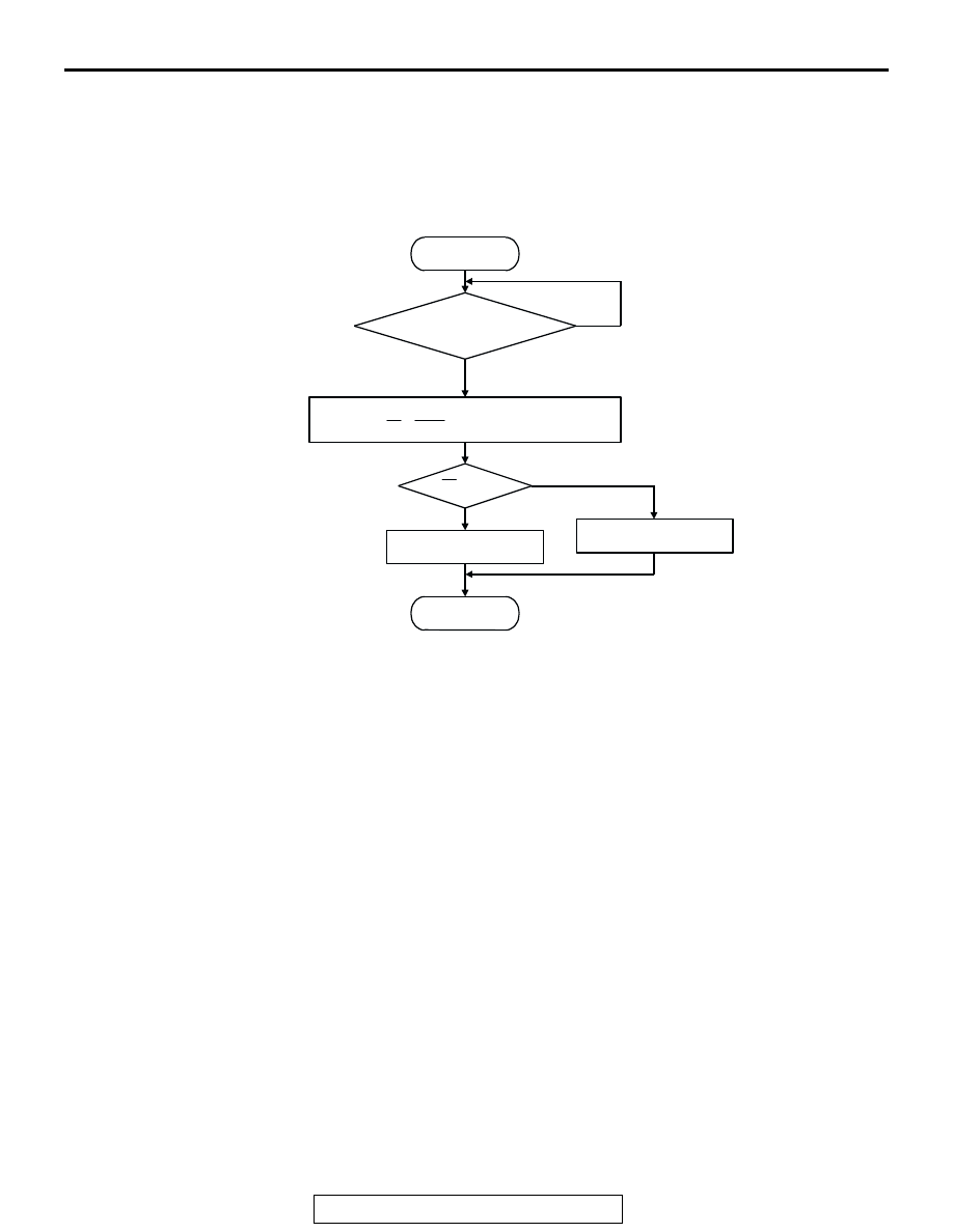
Logic Flow Chart
.
Check Conditions
• Engine speed is lower than 3,000 r/min.
• Accelerator pedal is open.
• Mass airflow is between 14 and 45 g/sec.
• More than 3 seconds have elapsed after the
above-mentioned three conditions have been
met.
• Intake air temperature is higher than −10°C
(14
°F).
• Barometric pressure is higher than 76 kPa (22.4
in.Hg).
• Under the closed loop air/fuel ratio control.
• Vehicle speed is 1.5 km/h (1.0 mph) or more.
• The PCM monitors for this condition for 5 cycles
of 10 seconds each during the drive cycle.
• Short-term fuel trim is higher than −25 percent
and lower than +25 percent.
• The cumulative mass airflow is higher than 1,638
g.
Judgment Criteria
• The cylinder 1, 4 heated oxygen sensor (rear)
signal frequency divided by cylinder 1, 4 heated
oxygen sensor (front) signal frequency = 0.7 or
more. <Federal>
or
• The cylinder 1, 4 heated oxygen sensor (rear)
signal frequency divided by cylinder 1, 4 heated
oxygen sensor (front) signal frequency = 0.6 or
more. <California>
.
OBD-II DRIVE CYCLE PATTERN
Refer to Diagnostic Function
− OBD-II Drive Cycle −
Procedure 3
− Catalytic Converter Monitor
.
TROUBLESHOOTING HINTS (The most likely
causes for this code to be set are:)
• Cylinder 1, 4 side catalytic converter deteriorated.
• Cylinder 1, 4 heated oxygen sensor failed.
• Exhaust leak.
• PCM failed.
START
MONITORING
CONDITIONS
MALFUNCTION
GOOD
END
NO
NO
YES
YES
Rf > R0
CALCULATE AVERAGE FREQUENCY
RATIO (Rf = Fr/Ff) OF SPECIFIED TIMES
R0: AVERAGE THRESHOLD VALUE.
AK302038