Mitsubishi Galant (2004+). Manual - part 874


  Index      Mitsubishi     Mitsubishi Galant - service repair manual 2004 year


Search            


Content   ..  872  873  874  875   ..


Mitsubishi Galant (2004+). Manual - part 874


MULTIPORT FUEL INJECTION (MFI) DIAGNOSIS

TSB Revision

MULTIPORT FUEL INJECTION (MFI) <2.4L ENGINE>

13A-313

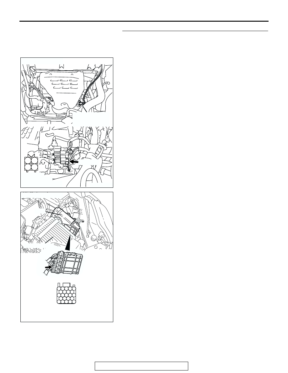
STEP 13. Check for short circuit to ground and harness 
damage between cylinder 2, 3 heated oxygen sensor 
(front) connector B-36 (terminal No. 4) and PCM connector 
B-22 (terminal No. 91).

Q: Is the harness wire in good condition?

YES : Go to Step 14.
NO :  Repair it. Then go to Step 15.

AK303830

1

2

3

4

AB

CONNECTOR: B-36 

B-36 (GR)

CYLINDER 2, 3
HEATED OXYGEN
SENSOR (FRONT)

HARNESS
CONNECTOR:
COMPONENT SIDE

AK303016

104

96

94

95

93 92 91

99 98 97

103 102 101 100

108 107 106 105

113 112 111 110 109

CONNECTOR: B-22

B-22 (B)

PCM

AB

HARNESS CONNECTOR: 
COMPONENT SIDE

AIR CLEANER

MULTIPORT FUEL INJECTION (MFI) DIAGNOSIS

TSB Revision

MULTIPORT FUEL INJECTION (MFI) <2.4L ENGINE>

13A-314

STEP 14. Check the cylinder 2, 3 heated oxygen sensor 
(front).

(1) Disconnect the cylinder 2, 3 heated oxygen sensor (front) 

connector B-36 and connect test harness special tool 
MB991316, to the connector on the cylinder 2, 3 heated 
oxygen sensor (front) side.

(2) Warm up the engine until engine coolant temperature 

reaches 80

°C (176°F) or higher.

(3) Perform a racing for 5 minutes or more with the engine 

speed of 4,500 r/min.

(4) Connect a digital voltage meter between terminal No. 2 

(black clip) and terminal No. 4 (white clip).

(5) While repeatedly revving the engine, measure the cylinder 

2, 3 heated oxygen sensor (front) output voltage.

Standard value: 0.6 

 1.0 volt

CAUTION

• Be very careful when connecting the jumper wires; 

incorrect connection can damage the heated oxygen 
sensor (front).

• Be careful the heater is broken when voltage of beyond 

8 volts is applied to the heated oxygen sensor (front) 
heater.
NOTE: If the sufficiently high temperature [of approximate 
400

°

C (752

°

F) or more] is not reached although the heated 

oxygen sensor (front) is normal, the output voltage would be 
possibly low although the rich air/fuel ratio. Therefore, if the 
output voltage is low, use a jumper wire to connect the ter-
minal No. 1 (red clip) and the terminal No. 3 (blue clip) of 
the heated oxygen sensor (front) with the positive terminal 
and the negative terminal of 8 volts power supply respec-
tively, then check again.

Q: Is the measured voltage between 0.6 and 1.0 volt?

YES : Replace the PCM. Then go to Step 15.
NO :  Replace the cylinder 2, 3 heated oxygen sensor 

(front). Then go to Step 15.

AK303830

1

2

3

4

AB

CONNECTOR: B-36 

B-36 (GR)

CYLINDER 2, 3
HEATED OXYGEN
SENSOR (FRONT)

HARNESS
CONNECTOR:
COMPONENT SIDE

AKX01624

HEATED
OXYGEN
SENSOR
COMPONENT
SIDE
CONNECTOR

MB991316

WHITE

BLACK

AN

MULTIPORT FUEL INJECTION (MFI) DIAGNOSIS

TSB Revision

MULTIPORT FUEL INJECTION (MFI) <2.4L ENGINE>

13A-315

STEP 15. Test the OBD-II drive cycle.

(1) Carry out a test drive with the drive cycle pattern. Refer to 

Diagnostic Function 

− OBD-II Drive Cycle − Procedure 6 − 

Other Monitor 

P.13A-5

.

(2) Check the diagnostic trouble code (DTC).
Q: Is DTC P0150 set?

YES : Retry the troubleshooting.
NO :  The inspection is complete.

DTC P0151: Cylinder 2, 3 Heated Oxygen Sensor Circuit Low Voltage (sensor 1)

100

99

92

91

93 94 95

96 97 98

101 102 103 104

105 106 107 108

109 110 111 112 113

52

51

53 54 55 56

57

58 59 60 61 62

63

64 65 66 67 68 69

70

71 72 73 74 75

76

77 78 79 80 81 82

83

AK303828

1

2

3

4

BLA

CK

BLA

CK

TO PCM

FROM MFI RELAY

WHITE

69

91

4

3

1

CYLINDER 2, 3
HEATED OXYGEN
SENSOR (FRONT)

POWERTRAIN CONTROL
MODULE (PCM)

B-36

MU802665

2

B-22

Cylinder 2, 3 Heated Oxygen Sensor (front) Circuit

B-21

MULTIPORT FUEL INJECTION (MFI) DIAGNOSIS

TSB Revision

MULTIPORT FUEL INJECTION (MFI) <2.4L ENGINE>

13A-316

.

CIRCUIT OPERATION

• A voltage corresponding to the oxygen concen-

tration in the exhaust gas is sent to the PCM (ter-
minal No. 91) from the output terminal (terminal 
No. 4) of the cylinder 2, 3 heated oxygen sensor 
(front).

• Terminal No. 2 of the cylinder 2, 3 heated oxygen 

sensor (front) is grounded with PCM (terminal 
No. 69).

.

TECHNICAL DESCRIPTION

• The cylinder 2, 3 heated oxygen sensor (front) 

detects the concentration of oxygen in the 
exhaust gas; it converts those data to voltage, 
and inputs the resulting signals to the PCM.

• When the cylinder 2, 3 heated oxygen sensor 

(front) begins to deteriorate, the heated oxygen 
sensor signal response becomes poor.

• The PCM forcibly varies the air/fuel mixture to 

make it leaner and richer, and checks the 
response speed of the cylinder 2, 3 heated oxy-
gen sensor (front). In addition, the PCM also 
checks for an open circuit in the cylinder 2, 3 
heated oxygen sensor (front) output line.

.

DESCRIPTIONS OF MONITOR METHODS
Cylinder 2, 3 heated oxygen sensor (front) output 

voltage stays low when air/fuel ratio is forced to 
be rich. The above procedure is repeated when 
oxygen sensor is inactive.

.

MONITOR EXECUTION
Continuous

.

MONITOR EXECUTION CONDITIONS (Other 
monitor and Sensor)

Other Monitor (There is no temporary DTC stored 

in memory for the item monitored below)

• Heated oxygen sensor heater (front) monitor

• Misfire monitor

• Fuel system monitor

Sensor (The sensor below is determined to be 

normal)

• Mass airflow sensor

• Engine coolant temperature sensor

• Intake air temperature sensor

• Barometric pressure sensor

• Throttle position sensor

• Accelerator pedal position sensor

.

AK303829AB

CONNECTOR: B-36 

B-36 (GR)

CYLINDER 2, 3
HEATED OXYGEN
SENSOR (FRONT)

AK303013

CONNECTORS: B-21, B-22

PCM

AB

AIR CLEANER

B-22 (B)

B-21 (B)


Content   ..  872  873  874  875   ..