Mitsubishi Galant (2004+). Manual - part 817


  Index      Mitsubishi     Mitsubishi Galant - service repair manual 2004 year


Search            


Content   ..  815  816  817  818   ..


Mitsubishi Galant (2004+). Manual - part 817


MULTIPORT FUEL INJECTION (MFI) DIAGNOSIS

TSB Revision

MULTIPORT FUEL INJECTION (MFI) <2.4L ENGINE>

13A-85

DIAGNOSIS

Required Special Tools:

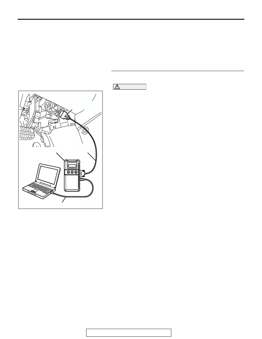
• MB991958: Scan Tool (MUT-III Sub Assembly)

• MB991824: V.C.I.

• MB991827: USB Cable

• MB991910: Main Harness A

• MB991923: Power Plant ECU Check Harness

STEP 1. Using scan tool MB991958, check data list item 95: 
Manifold Absolute Pressure Sensor.

CAUTION

To prevent damage to scan tool MB991958, always turn the 
ignition switch to the "LOCK" (OFF) position before con-
necting or disconnecting scan tool MB991958.
(1) Connect scan tool MB991958 to the data link connector.
(2) Turn the ignition switch to the "ON" position.
(3) Set scan tool MB991958 to the data reading mode for item 

95, Manifold absolute Pressure Sensor.

• When altitude is 0 m (0 foot), 101 kPa (29.8 in.Hg).

• When altitude is 600 m (1,969 feet), 95 kPa (28.1 in.Hg).

• When altitude is 1,200 m (3,937 feet), 88 kPa (26.0 

in.Hg).

• When altitude is 1,800 m (5,906 feet), 81 kPa (23.9 

in.Hg).

(4) Start the engine.

• When the engine is idling, 16 − 36 kPa (4.7 − 10.6 

in.Hg).

• When the engine is suddenly revved, manifold absolute 

pressure varies.

(5) Turn the ignition switch to the "LOCK" (OFF) position.
Q: Is the sensor operating properly?

YES : It can be assumed that this malfunction is intermittent. 

Refer to GROUP 00, How to Use 
Troubleshooting/Inspection Service Points 

P.00-6

.

NO :  Go to Step 2.

AK303804AB

MB991910

DATA LINK
CONNECTOR

MB991824

MB991827

MULTIPORT FUEL INJECTION (MFI) DIAGNOSIS

TSB Revision

MULTIPORT FUEL INJECTION (MFI) <2.4L ENGINE>

13A-86

STEP 2. Measure the sensor supply voltage at manifold 
absolute pressure sensor connector B-02 by backprobing.
(1) Do not disconnect the connector B-02.
(2) Turn the ignition switch to the "ON" position.

(3) Measure the voltage between terminal No. 3 and ground by 

backprobing.

• Voltage should be between 4.9 and 5.1 volts.

(4) Turn the ignition switch to the "LOCK" (OFF) position.
Q: Is the measured voltage between 4.9 and 5.1 volts?

YES : Go to Step 8.
NO :  Go to Step 3.

STEP 3. Check harness connector B-21 at PCM for 
damage.
Q: Is the harness connector in good condition?

YES : Go to Step 4.
NO :  Repair or replace it. Refer to GROUP 00E, Harness 

Connector Inspection 

P.00E-2

. Then go to Step 12.

AK303809

1

2

3

AB

CONNECTOR: B-02

B-02 (B)

HARNESS CONNECTOR:
COMPONENT SIDE

3

2

1

AK203036

B-02 HARNESS 
CONNECTOR: 
HARNESS SIDE

AG

AK303018

55

56

54 53 52 51

57

62 61 60 59 58

63

69 68 67 66 65 64

70

75 74 73 72 71

76

82 81 80 79 78 77

83

CONNECTOR: B-21

PCM

AB

HARNESS CONNECTOR: 
COMPONENT SIDE

AIR CLEANER

B-21 (B)

MULTIPORT FUEL INJECTION (MFI) DIAGNOSIS

TSB Revision

MULTIPORT FUEL INJECTION (MFI) <2.4L ENGINE>

13A-87

STEP 4. Measure the sensor supply voltage at PCM 
connector B-21 by using power plant ECU check harness 
special tool MB991923.
(1) Disconnect the all PCM connectors and connect power 

plant ECU check harness special tool MB991923 between 
the separated connectors.

(2) Turn the ignition switch to the "ON" position.

AK303018

55

56

54 53 52 51

57

62 61 60 59 58

63

69 68 67 66 65 64

70

75 74 73 72 71

76

82 81 80 79 78 77

83

CONNECTOR: B-21

PCM

AB

HARNESS CONNECTOR: 
COMPONENT SIDE

AIR CLEANER

B-21 (B)

AK202989

55

56

54 53 52 51

57

62 61 60 59 58

63

69 68 67 66 65 64

70

75 74 73 72 71

76

82 81 80 79 78 77

83

AB

POWER PLANT ECU 
CHECK HARNESS CONNECTOR

MB991923

PCM

MULTIPORT FUEL INJECTION (MFI) DIAGNOSIS

TSB Revision

MULTIPORT FUEL INJECTION (MFI) <2.4L ENGINE>

13A-88

(3) Measure the voltage between terminal No. 68 and ground.

• Voltage should be between 4.9 and 5.1 volts.

(4) Turn the ignition switch to the "LOCK" (OFF) position.
Q: Is the measured voltage between 4.9 and 5.1 volts?

YES : Go to Step 7.
NO :  Go to Step 5.

STEP 5. Check harness connector B-02 at the manifold 
absolute pressure sensor for damage.
Q: Is the connector in good condition?

YES : Go to Step 6.
NO :  Repair or replace it. Refer to GROUP 00E, Harness 

Connector Inspection 

P.00E-2

. Then go to Step 12.

55

56

54 53 52 51

57

62 61 60 59 58

63

69 68 67 66 65 64

70

75 74 73 72 71

76

82 81 80 79 78 77

83

AK203037AB

POWER PLANT ECU 
CHECK HARNESS 
CONNECTOR 

AK303809

1

2

3

AB

CONNECTOR: B-02

B-02 (B)

HARNESS CONNECTOR:
COMPONENT SIDE


Content   ..  815  816  817  818   ..