Mitsubishi Galant (2004+). Manual - part 781


  Index      Mitsubishi     Mitsubishi Galant - service repair manual 2004 year


Search            


Content   ..  779  780  781  782   ..


Mitsubishi Galant (2004+). Manual - part 781


ON-VEHICLE SERVICE

TSB Revision

HEATER, AIR CONDITIONING AND VENTILATION

55A-263

ON-VEHICLE SERVICE

REFRIGERANT LEVEL TEST

M1552008400408

Use the refrigerant recovery station to remove all of the refrig-
erant, and then calculate the amount of the refrigerant and 
charge it.

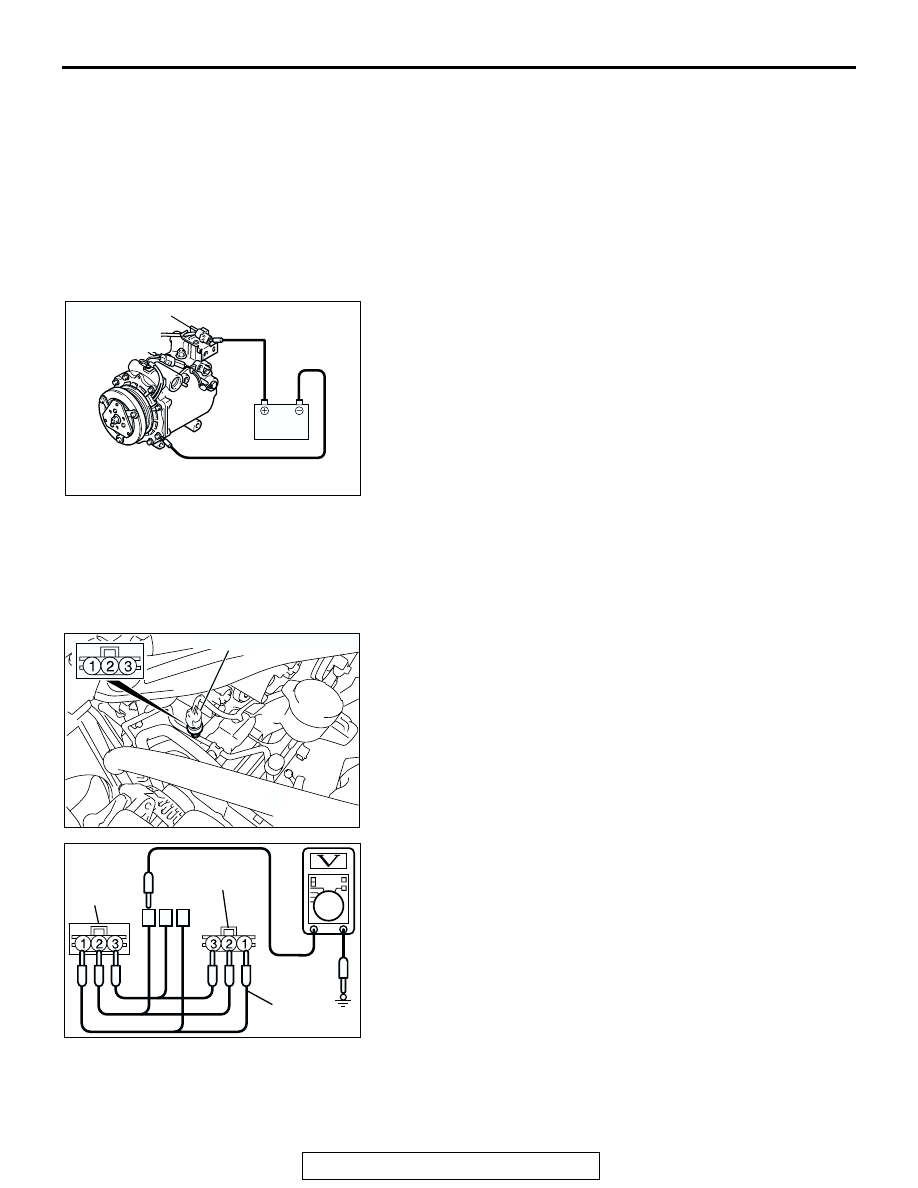
A/C COMPRESSOR CLUTCH TEST

M1552019900032

1. Disconnect the air conditioning compressor clutch connector 

to the air conditioning compressor clutch.

2. Connect positive battery voltage directly to the connector for 

the air conditioning compressor clutch.

3. If the air conditioning compressor clutch is normal, there will 

be a "click." If the pulley and armature do not make contact 
("no click"), there is a malfunction.

SIMPLE INSPECTION OF THE A/C PRESSURE 
SENSOR

M1552014700118

1. Assemble a gauge manifold on the high pressure service 

valve.

2. Disconnect the A/C pressure sensor connector and connect 

special tool test harness MB991658 as shown in the illustra-
tion.

3. Turn ON the engine and then turn ON the air conditioner 

switch.

AC206292AB

A/C COMPRESSOR 
CLUTCH 
CONNECTOR

AC305034

A/C PRESSURE SENSOR

AD

AC307368

A/C 
PRESSURE 
SENSOR 
SIDE

MB991658

AB

HARNESS SIDE

ON-VEHICLE SERVICE

TSB Revision

HEATER, AIR CONDITIONING AND VENTILATION

55A-264

4. At this time, check to see that the voltage of A/C pressure 

sensor terminal No. 2 reflects the specifications of the fig-
ure.
NOTE: The allowance shall be defined as 

±

5%.

COMPRESSOR DRIVE BELT ADJUSTMENT

M1552001000357

Refer to GROUP 00, Maintenance Service 

− Drive Belts 

P.00-43

CHARGING 

M1552001200403

Use the refrigerant recovery station to charge the refrigerant.

METHOD BY USING REFRIGERANT RECOVERY 
AND RECYCLING UNIT

Using the refrigerant recovery and recycling unit, refill the 
refrigerant.
NOTE: Refer to the Refrigerant Recovery and Recycling Unit’s 
Instruction Manual for operation of the unit.

DISCHARGING SYSTEM

Use the refrigerant recovery unit to discharge refrigerant gas 
from the system.
NOTE: Refer to the Refrigerant Recovery and Recycling Unit’s 
Instruction Manual for operation of the unit.

REFILLING OF OIL IN THE A/C SYSTEM

Too little oil will provide inadequate compressor lubrication and 
cause a compressor failure. Too much oil will increase dis-
charge air temperature.
When a compressor is installed at the factory, it contains 140 
cm

3

 (4.7 fl.oz) of refrigerant oil. While the A/C system is in 

operation, the oil is carried through the entire system by the 
refrigerant. Some of this oil will be trapped and retained in vari-
ous parts of the system.
When the following system components are changed, it is nec-
essary to add oil to the system to replace the oil being removed 
with the component.

Compressor oil: SUN PAG 56
Quantity:

Evaporator: 60 cm

3

 (2.0 fl.oz)

Condenser: 15 cm

3

 (0.5 fl.oz)

Suction hose: 10 cm

3

 (0.3 fl.oz)

AC208297AB

REFRIGERANT PRESSURE (MPa)

OUTPUT VOLTAGE 

(V)

0

1

2

3

5

4

1

2

3

ON-VEHICLE SERVICE

TSB Revision

HEATER, AIR CONDITIONING AND VENTILATION

55A-265

PERFORMANCE TEST 

M1552001400388

The vehicles to be tested should be parked out of direct sun-
light.
1. Close the high and low-pressure valve of the gauge 

manifold.

2. Connect the charging hose (blue) to the low-pressure valve 

and connect the charging hose (red) to the high-pressure 
valve of the gauge manifold.

3. Install the quick joint (for low-pressure) to the charging hose 

(blue), and connect the quick joint (for high-pressure) to the 
charging hose (red).

CAUTION

• To connect the quick joint, press section A firmly 

against the service valve until a click is heard.

• When connecting, run your hand along the hose while 

pressing to ensure that there are no bends in the hose.

4. Connect the quick joint (for low-pressure) to the 

low-pressure service valve and connect the quick joint (for 
high-pressure) to the high-pressure service valve.
NOTE: The high-pressure service valve is on the A/C pipe 
and the low-pressure service valve is on the suction hose.

5. Start the engine.
6. Set the A/C controls as follows:

• A/C switch: A/C − ON position

• Mode selection: FACE position

• Temperature control: MAXIMUM COOLING position

• Air selection: RECIRCULATION position

• Blower switch: Maximum air volume 

7. Adjust engine speed to 1,500 r/min with A/C clutch engaged.
8. Engine should be warmed up with doors and windows 

closed.

9. Insert a thermometer in the center air outlet and operate the 

engine for 20 minutes.
NOTE: If the A/C clutch cycles, take the reading before the 
clutch disengages.

10.Note the discharge air temperature.

AC001388

LOW-PRESSURE
VALVE

HIGH-PRESSURE
VALVE

GAUGE MANIFOLD

CHARGING
HOSE (RED)

A

SLEEVE

CHARGING
HOSE (BLUE)

ADAPTOR
VALVE
(FOR
LOW-PRES-
SURE)

ADAPTOR
VALVE
(FOR HIGH-
PRESSURE)

LOW-
PRESSURE
SERVICE
VALVE

HIGH-
PRESSURE
SERVICE
VALVE

AB

AC306951

AB

THERMOMETER

ON-VEHICLE SERVICE

TSB Revision

HEATER, AIR CONDITIONING AND VENTILATION

55A-266

Performance Temperature Chart

REFRIGERANT LEAK REPAIR PROCEDURE

M1552001500299

LOST CHARGE

If the system has lost all charge due to a leak:
1. Evacuate the system. (Refer to 

P.55A-264

).

2. Charge the system with approximately 0.453 kg (1 

pound) of refrigerant.

3. Check for leaks.
4. Discharge the system.
5. Repair leaks.

CAUTION

Replacement filter-drier units must be sealed 
while in storage. The drier used in these units will 
saturate water quickly upon exposure to the 
atmosphere. When installing a drier, have all 
tools and supplies ready for quick assembly to 
avoid keeping the system open any longer than 
necessary.
6. Replace receiver drier.
7. Evacuate and charge system.

LOW CHARGE

If the system has not lost all of its refrigerant charge; 
locate and repair all leaks. If it is necessary to 
increase the system pressure to find the leak 
(because of an especially low charge) add refriger-
ant. If it is possible to repair the leak without dis-
charging the refrigerant system, use the procedure 
for correcting low refrigerant level.

HANDLING TUBING AND FITTINGS

Kinks in the refrigerant tubing or sharp bends in the 
refrigerant hose lines will greatly reduce the capacity 
of the entire system. High pressures are produced in 
the system when it is operating. Extreme care must 
be exercised to make sure that all connections are 
pressure tight. Dirt and moisture can enter the sys-
tem when it is opened for repair or replacement of 
lines or components. The following precautions must 
be observed. The system must be completely dis-
charged before opening any fitting of connection in 
the refrigeration system. Open fittings with caution 
even after the system has been discharged. If any 
pressure is noticed as a fitting is loosened, allow 
trapped pressure to bleed off very slowly.
Never attempt to rebend formed lines to fit. Use the 
correct line for the installation you are servicing. A 
good rule for the flexible hose lines is keep the radius 
of all bends at least 10 times the diameter of the 
hose.
Sharper bends will reduce the flow of refrigerant. The 
flexible hose lines should be routed so that they are 
at least 80 mm (3.1 inches) from the exhaust mani-
fold. It is good practice to inspect all flexible hose 
lines at least once a year to make sure they are in 
good condition and properly routed.
On standard plumbing fittings with O-rings, these 
O-rings are not reusable.

COMPRESSOR NOISE CHECK

M1552008700294

You must first know the conditions when the noise 
occurs. These conditions are: weather, vehicle 
speed, in gear or neutral, engine temperature or any 
other special conditions.
Noises that develop during A/C operation can often 
be misleading. For example: what sounds like a 
failed front bearing or connecting rod, may be 
caused by loose bolts, nuts, mounting brackets, or a 
loose clutch assembly. Verify accessory drive belt 
tension (power steering or generator).

Improper accessory drive belt tension can cause a 
misleading noise when the compressor is engaged 
and little or no noise when the compressor is disen-
gaged.
Drive belts are speed-sensitive. That is, at different 
engine speeds, and depending upon belt tension, 
belts can develop unusual noises that are often mis-
taken for mechanical problems within the compres-
sor.

GARAGE AMBIENT AIR TEMPERATURE 

°

(

°F)

20 (68)

25 (77)

30 (86)

35 (95)

Discharge air temperature 

°C (°F)

− 6 (33.8 − 42.8)

Compressor high pressure kPa (psi)

1274 

− 1666 (185 − 242)

Compressor low pressure kPa (psi)

49 

− 294 (7 − 43)


Content   ..  779  780  781  782   ..