Mitsubishi Galant (2004+). Manual - part 771


  Index      Mitsubishi     Mitsubishi Galant - service repair manual 2004 year


Search            


Content   ..  769  770  771  772   ..


Mitsubishi Galant (2004+). Manual - part 771


MANUAL A/C DIAGNOSIS

TSB Revision

HEATER, AIR CONDITIONING AND VENTILATION

55A-223

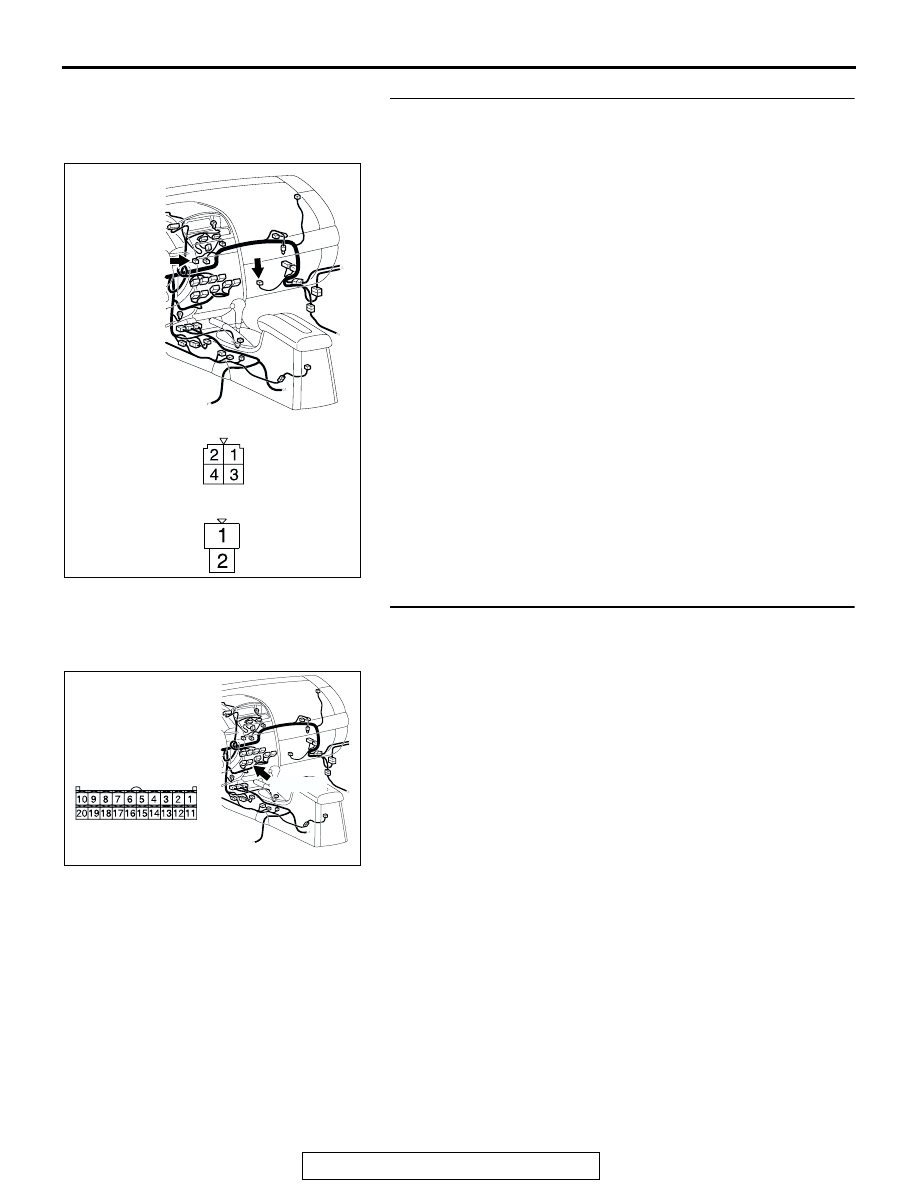
STEP 5. Check the wiring harness between power 
transistor connector C-104 (terminal 4) and blower motor 
connector C-115 (terminal 2).

Q: Is the wiring harness between power transistor 

connector C-104 (terminal 4) and blower motor 
connector C-115 (terminal 2) in good condition?
YES : 
 Go to Step 6.
NO :  Repair the wiring harness. The blower motor should 

operate normally.

STEP 6. Check A/C-ECU connector C-15 for loose, 
corroded or damaged terminals, or terminals pushed back 
in the connector.

Q: Is A/C-ECU connector C-15 in good condition?

YES : Go to Step 7.
NO :  Repair or replace the connector. Refer to GROUP 

00E, Harness Connector Inspection 

P.00E-2

.The 

blower motor should operate normally.

AC305234

C-104

C-115

HARNESS SIDE

C-104

HARNESS SIDE

C-115

AR

CONNECTORS: C-104, C-115

AC305233

CONNECTOR: C-15

BG

C-105 (B)

HARNESS SIDE

MANUAL A/C DIAGNOSIS

TSB Revision

HEATER, AIR CONDITIONING AND VENTILATION

55A-224

STEP 7. Check the wiring harness between power 
transistor connector C-104 (terminals 1 and 3) and 
A/C-ECU connector C-15 (terminals 17 and 18).

Q: Are the wiring harness between power transistor 

connector C-104 (terminals 1 and 3) and A/C-ECU 
connector C-15 (terminals 17 and 18) in good condition?
YES : 
 Go to Step 8.
NO :  Repair the wiring harness. The blower motor should 

operate normally.

STEP 8. Replace the power transistor.
Q: Does the blower motor operate normally?

YES : It can be assumed that this malfunction is intermittent. 

Refer to GROUP 00, How to Use 
Troubleshooting/Inspection Service Points 

− How to 

Use Troubleshooting/Inspection Service Points 

P.00-6

.

NO :  Replace the A/C-ECU. Check that the air conditioning 

works normally. 

AC305234

C-104

HARNESS SIDE

C-104

HARNESS SIDE

C-15

AT

CONNECTORS: C-15, C-104

C-15 (B)

MANUAL A/C DIAGNOSIS

TSB Revision

HEATER, AIR CONDITIONING AND VENTILATION

55A-225

INSPECTION PROCEDURE 7: The A/C Indicator Flashes.

.

TECHNICAL DESCRIPTION (COMMENT)
If the A/C indicator flashes, inadequate refrigerant 
quantity, the ambient air temperature sensor circuit 
or the A/C pressure sensor circuit is suspected.

.

TROUBLESHOOTING HINTS

• Malfunction of the A/C pressure sensor

• Malfunction of the ambient air temperature sen-

sor

• Malfunction of the A/C-ECU

A/C-ECU

A/C PRESSURE
SENSOR

A/C Pressure Sensor Circuit

AC305206

A-30 (B)

AZ

CONNECTOR: A-30

AC305233

C-16 (B)

C-15 (B)

CONNECTORS: C-15, C-16

BE

AC305231

CONNECTOR: C-29

AH

MANUAL A/C DIAGNOSIS

TSB Revision

HEATER, AIR CONDITIONING AND VENTILATION

55A-226

DIAGNOSIS

Required Special Tools:

• MB991223: Test Harness Set

•  MB991958: Scan Tool (MUT-III Sub Assembly)

• MB991824: Vehicle Communication Interface (V.C.I.)

• MB991827: MUT-III USB Cable

• MB991910: MUT-III Main Harness A (Vehicles with CAN 

communication system)

STEP 1. Using scan tool MB991958, read the diagnostic 
trouble code.

Check if an A/C-ECU DTC is set.

1. Connect scan tool MB991958 to the data link connector.
2. Turn the ignition switch to the "ON" position.
3. Check if the DTC is set.
4. Turn the ignition switch to the "LOCK" (OFF) position.

Q: Is the check result satisfactory?

YES : Go to Step 2.
NO :  Refer to DIAGNOSTIC TROUBLE CODE CHART 

P.55A-59

.

AC206894

AB

MB991910

DATA LINK

CONNECTOR

MB991824

MB991827


Content   ..  769  770  771  772   ..