Mitsubishi Galant (2004+). Manual - part 756


  Index      Mitsubishi     Mitsubishi Galant - service repair manual 2004 year


Search            


Content   ..  754  755  756  757   ..


Mitsubishi Galant (2004+). Manual - part 756


MANUAL A/C DIAGNOSIS

TSB Revision

HEATER, AIR CONDITIONING AND VENTILATION

55A-163

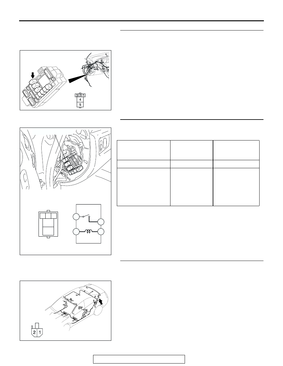
STEP 2. Check defogger relay connector C-201 for loose, 
corroded or damaged terminals, or terminals pushed back 
in the connector.

Q: Is defogger relay connector C-201 in good condition?

YES : Go to Step 3.
NO :  Repair or replace the connector. Refer to GROUP 

00E, Harness Connector Inspection 

P.00E-2

. The 

defogger system should work normally.

STEP 3. Check the defogger relay continuity.

Follow the table below to check the defogger relay for continu-
ity.

Q: Is the defogger relay in good condition?

YES : Go to Step 4.
NO :  Replace the defogger relay. The defogger system 

should work normally.

STEP 4. Check defogger relay connector D-14 for loose, 
corroded or damaged terminals, or terminals pushed back 
in the connector.

Q: Is defogger relay connector D-14 in good condition?

YES : Go to Step 5.
NO :  Repair or replace the connector. Refer to GROUP 

00E, Harness Connector Inspection 

P.00E-2

. The 

defogger system should work normally.

AC305415BE

CONNECTOR: C-201

JUNCTION BLOCK SIDE

JUNCTION BLOCK 
(FRONT VIEW)

BATTERY VOLTAGE CONNECT 

TESTER 
BETWEEN

SPECIFIED 
CONDITION

Not applied

− 5

Open Circuit

• Connect terminal 1 

to the positive 
battery terminal

• Connect terminal 3 

to the negative 
battery terminal

− 5

Less than 2 ohms

AC209677

4

5

1 2 3

5

1

4

3

DEFOGGER RELAY

AD

AC305268

CONNECTOR: D-14

AJ

HARNESS SIDE

MANUAL A/C DIAGNOSIS

TSB Revision

HEATER, AIR CONDITIONING AND VENTILATION

55A-164

STEP 5. Measure the voltage at choke coil connector D-14. 

(1) Disconnect choke coil connector D-14, and measure the 

voltage at the harness side.

(2) Disconnect A/C-ECU connector C-09 and ground harness 

side terminal No.27.

(3) Turn the ignition switch to the "ON" position.

(4) Measure the voltage between choke coil connector D-14 

terminal No.1 and ground.

• The measured value should be approximately 12 volts 

(battery positive voltage).

Q: Is the measured voltage approx. 12 volts?

YES :  Go to Step 13.
NO :   Go to Step 6.

AC305268

CONNECTOR: D-14

AJ

HARNESS SIDE

AC305233

C-09 (B)

HARNESS SIDE

21

22

23

24

25

26

27

28

29

30

31

32

BB

CONNECTOR: C-09

AC306468

21

22

23

24

25

26

27

28

29

30

31

32

AC306468

CONNECTOR C-09 
(HARNESS SIDE)

AE

AC209365GZ

CONNECTOR D-14 
(HARNESS SIDE)

MANUAL A/C DIAGNOSIS

TSB Revision

HEATER, AIR CONDITIONING AND VENTILATION

55A-165

STEP 6. Measure the voltage at defogger relay connector 
C-201. 

(1) Disconnect defogger relay connector C-201, and measure 

the voltage at the junction block side.

(2) Measure the voltage between terminal 5 and ground.

• The measured value should be approximately 12 volts 

(battery positive voltage).

Q: Is the measured voltage approx. 12 volts?

YES :  Go to Step 8.
NO :   Go to Step 7.

STEP 7. Check the wiring harness between defogger relay 
connector C-201 (terminal 5) and the fusible link (1).

AC305415BE

CONNECTOR: C-201

JUNCTION BLOCK SIDE

JUNCTION BLOCK 
(FRONT VIEW)

AC209365

CONNECTOR C-201 
(JUNCTION BLOCK SIDE)

HA

AC305416

CONNECTORS: C-201, C-216

JUNCTION BLOCK 
(FRONT VIEW)

HARNESS SIDE

C-201

C-216 (B)

C-216

C-201

JUNCTION BLOCK SIDE

AP

MANUAL A/C DIAGNOSIS

TSB Revision

HEATER, AIR CONDITIONING AND VENTILATION

55A-166

NOTE: Also check intermediate connector C-29 and junction 
block connector C-216 for loose, corroded, or damaged termi-
nals, or terminals pushed back in the connector. If intermediate 
connector C-29 and junction block connector C-216 is dam-
aged, repair or replace the connector as described in GROUP 
00E, Harness Connector Inspection 

P.00E-2

.

Q: Is the wiring harness between defogger relay connector 

C-201(terminal 5) and the fusible link (1) in good 
condition?
YES : 
Check that the defogger system works normally.
NO :  Repair the wiring harness. Check that the defogger 

system works normally.

STEP 8. Measure the voltage at defogger relay connector 
C-201. 

(1) Disconnect defogger relay connector C-201, and measure 

the voltage at the junction block side.

(2) Turn the ignition switch to the "ON" position.

(3) Measure the voltage between terminal 1 and ground.

• The measured value should be approximately 12 volts 

(battery positive voltage).

Q: Is the measured voltage approx. 12 volts?

YES :  Go to Step 10.
NO :   Go to Step 9.

AC305231AI

CONNECTOR: C-29

AC305415BE

CONNECTOR: C-201

JUNCTION BLOCK SIDE

JUNCTION BLOCK 
(FRONT VIEW)

AC209365HB

CONNECTOR C-201 
(JUNCTION BLOCK SIDE)


Content   ..  754  755  756  757   ..