Mitsubishi Galant (2004+). Manual - part 754


  Index      Mitsubishi     Mitsubishi Galant - service repair manual 2004 year


Search            


Content   ..  752  753  754  755   ..


Mitsubishi Galant (2004+). Manual - part 754


MANUAL A/C DIAGNOSIS

TSB Revision

HEATER, AIR CONDITIONING AND VENTILATION

55A-155

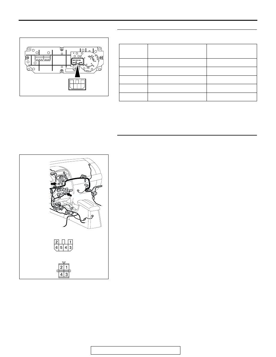
STEP 6. Check the blower switch continuity.

Follow the table below to check the blower switch for continuity.

Q: Is the blower switch continuity in good condition?

YES : Go to Step 7.
NO :  Replace the blower switch. The blower motor should 

operate normally.

STEP 7. Check the wiring harness blower switch 
connector C-14 (terminals 1, 6 and 2) and resistor 
connector C-103 (terminals 3, 1 and 4).

Q: Are the wiring harness between blower switch 

connector C-14 (terminals 1, 6 and 2) and resistor 
connector C-103 (terminals 3, 1 and 4) in good 
condition?
YES : 
It can be assumed that this malfunction is intermittent. 

Refer to GROUP 00, How to Use 
Troubleshooting/Inspection Service Points 

P.00-6

.

NO :  Repair the wiring harness. The blower motor should 

operate normally.

SWITCH 
POSITION

TESTER CONNECTION 
(CONNECTOR A) 

SPECIFIED 
CONDITION

0 (OFF)

− 4, 2− 4, 4 − 5, 4 − 6

Open circuit

1 (LO)

− 4

Less than 2 ohms

2 (ML)

− 6

Less than 2 ohms

3 (MH)

− 4

Less than 2 ohms

4 (HI)

− 5

Less than 2 ohms

AC306526

1
3 4 5 6

2

AC305234

CONNECTORS: C-14, C-103

C-103

C-14

HARNESS SIDE

C-14

HARNESS SIDE

C-103

AL

MANUAL A/C DIAGNOSIS

TSB Revision

HEATER, AIR CONDITIONING AND VENTILATION

55A-156

INSPECTION PROCEDURE 7: The A/C Indicator Flashes.

.

TECHNICAL DESCRIPTION (COMMENT)
If the A/C indicator flashes, inadequate refrigerant 
quantity, the ambient air temperature sensor circuit 
or the A/C pressure sensor circuit is suspected.

.

TROUBLESHOOTING HINTS

• Malfunction of the A/C pressure sensor

• Malfunction of the ambient air temperature sen-

sor

• Malfunction of the A/C-ECU

A/C-ECU

A/C PRESSURE
SENSOR

A/CPressure Sensor Circuit

AC305206

A-30 (B)

AZ

CONNECTOR: A-30

AC305233

C-10 (B)

AY

CONNECTOR: C-10

AC305231

CONNECTOR: C-29

AH

MANUAL A/C DIAGNOSIS

TSB Revision

HEATER, AIR CONDITIONING AND VENTILATION

55A-157

DIAGNOSIS

Required Special Tools:

• MB991223: Test Harness Set

•  MB991958: Scan Tool (MUT-III Sub Assembly)

• MB991824: Vehicle Communication Interface (V.C.I.)

• MB991827: MUT-III USB Cable

• MB991910: MUT-III Main Harness A (Vehicles with CAN 

communication system)

STEP 1. Using scan tool MB991958, read the diagnostic 
trouble code.

Check if an A/C-ECU DTC is set.

1. Connect scan tool MB991958 to the data link connector.
2. Turn the ignition switch to the "ON" position.
3. Check if the DTC is set.
4. Turn the ignition switch to the "LOCK" (OFF) position.

Q: Is the check result satisfactory?

YES : Go to Step 2.
NO :  Refer to DIAGNOSTIC TROUBLE CODE CHART 

P.55A-10

.

AC305412

AB

MB991910

DATA LINK

CONNECTOR

MB991824

MB991827

MANUAL A/C DIAGNOSIS

TSB Revision

HEATER, AIR CONDITIONING AND VENTILATION

55A-158

STEP 2. Using scan tool MB991958, check data list item 04: 
A/C pressure sensor.

CAUTION

To prevent damage to scan tool MB991958, always turn the 
ignition switch to the "LOCK" (OFF) position before con-
necting or disconnecting scan tool MB991958.
(1) Connect scan tool MB991958 to the data link connector.
(2) Assemble a manifold gauge onto the high pressure service 

valve.

(3) Turn ON the engine and then turn ON the air conditioner 

switch.

(4) Set scan tool MB991958 to the data reading mode for item 

04: A/C pressure sensor.

• Check that the refrigerant pressure matches the dis-

played value on the scan tool.

(5) Turn the ignition switch to the "LOCK" (OFF) position.
Q: Is the sensor within the specified range?

YES : Go to Step 7.
NO :  Go to Step 3.

STEP 3. Check A/C pressure sensor connector A-30 for 
loose, corroded or damaged terminals, or terminals 
pushed back in the connector.

Q: Is A/C pressure sensor connector A-30 in good 

condition?
YES : 
Go to Step 4.
NO :  Repair or replace the connector. Refer to GROUP 

00E, Harness Connector Inspection 

P.00E-2

. Check 

that the air conditioning works normally. 

AC305412

AB

MB991910

DATA LINK

CONNECTOR

MB991824

MB991827

AC305206

CONNECTOR: A-30

AY

HARNESS SIDE

A-30 (B)


Content   ..  752  753  754  755   ..